Lost Communication with Wiper ECU LIN (B1245)
DESCRIPTION
The main body
ECU (multiplex network body ECU) and windshield wiper motor assembly
communicate via LIN communication. The main body ECU (multiplex network
body ECU) stores this DTC if communication becomes abnormal.
|
DTC No. | Detection Item |
DTC Detection Condition | Trouble Area |
Memory | DTC Output from |
|
B1245 | Lost Communication with Wiper ECU LIN |
- Battery voltage is 9.5 V or more
- Communication malfunction between the main body ECU (multiplex network body ECU) and windshield wiper motor assembly
|
- Windshield wiper motor assembly
- Main body ECU (multiplex network body ECU)
- WIPER relay
- Harness or connector
| â—‹ |
Main body ECU (multiplex network body ECU) |
WIRING DIAGRAM
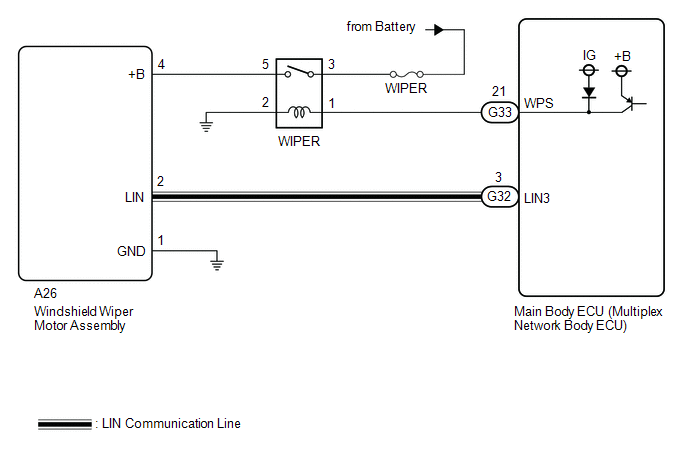
CAUTION / NOTICE / HINT
NOTICE:
Before replacing the main body ECU (multiplex network body ECU), refer to Registration.
Click here 
PROCEDURE
(a) Connect the Techstream to the DLC3.
(b) Turn the engine switch on (IG).
(c) Turn the Techstream on.
(d) Enter the following menus: Body Electrical / Main Body / Trouble Codes.
(e) Check for DTCs.
Body Electrical > Main Body > Trouble Codes
|
Result | Proceed to |
|
Only DTC B1245 is output |
A |
| DTC B1245 and B1373 are output |
B |
| B |
 | GO TO B1373 |
|
A |
 | |
| 2. |
CHECK HARNESS AND CONNECTOR (WINDSHIELD WIPER MOTOR ASSEMBLY - MAIN BODY ECU (MULTIPLEX NETWORK BODY ECU)) |
(a) Disconnect the A26 windshield wiper motor assembly connector.
(b) Disconnect the G32 main body ECU (multiplex network body ECU) connector.
(c) Measure the resistance according to the value(s) in the table below.
Standard Resistance:
|
Tester Connection | Condition |
Specified Condition |
|
G32-3 (LIN3) - A26-2 (LIN) |
Always | Below 1 Ω |
| NG |
 | REPAIR OR REPLACE HARNESS OR CONNECTOR |
|
OK |
 | |
| 3. |
CHECK MAIN BODY ECU (MULTIPLEX NETWORK BODY ECU) |
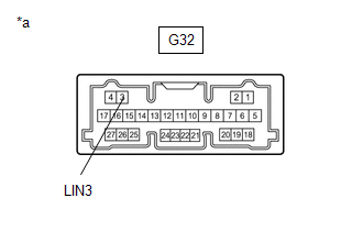
|
*a | Component without harness connected
(Main Body ECU (Multiplex Network Body ECU) |
(a) Check for pulses according to the value(s) in the table below.
Standard Voltage:
|
Tester Connection | Condition |
Specified Condition |
|
G32-3 (LIN3) - Body ground |
Engine switch off | Below 1 V |
|
Engine switch on (IG) |
Pulse generation |
| NG |
 | REPLACE MAIN BODY ECU (MULTIPLEX NETWORK BODY ECU) |
|
OK |
 | |
| 4. |
PERFORM ACTIVE TEST USING TECHSTREAM |
(a) Connect the Techstream to the DLC3.
(b) Turn the engine switch on (IG).
(c) Turn the Techstream on.
(d) Enter following menus: Body Electrical / Main Body / Active Test.
(e) Perform the Active Test according to the display on the Techstream.
Body Electrical > Main Body > Active Test
|
Tester Display | Measurement Item |
Control Range | Diagnostic Note |
|
Wiper Power Relay | Function to operate the WIPER relay |
OFF or ON | - |
Body Electrical > Main Body > Active Test
|
Tester Display |
| Wiper Power Relay |
OK:
WIPER relay operates normally.
| NG |
 | GO TO STEP 10 |
|
OK |
 | |
| 5. |
CHECK HARNESS AND CONNECTOR (WINDSHIELD WIPER MOTOR ASSEMBLY - BODY GROUND) |
(a) Measure the resistance according to the value(s) in the table below.
Standard Resistance:
|
Tester Connection | Condition |
Specified Condition |
|
A26-1 (GND) - Body ground |
Always | Below 1 Ω |
| NG |
 | REPAIR OR REPLACE HARNESS OR CONNECTOR |
|
OK |
 | |
| 6. |
CHECK HARNESS AND CONNECTOR (POWER SOURCE - WINDSHIELD WIPER MOTOR ASSEMBLY) |
(a) Measure the voltage according to the value(s) in the table below.
Standard Voltage:
|
Tester Connection | Condition |
Specified Condition |
|
A26-4 (+B) - Body ground |
Engine switch on (IG) |
11 to 14 V |
|
Less than approximately 60 seconds after engine switch turned off |
11 to 14 V |
|
Approximately 60 seconds or more after engine switch turned off |
Below 1 V |
| OK |
 | REPLACE WINDSHIELD WIPER MOTOR ASSEMBLY |
|
NG |
 | |
(a) Inspect the WIPER relay.
Click here 
| NG |
 | REPLACE WIPER RELAY |
|
OK |
 | |
| 8. |
CHECK HARNESS AND CONNECTOR (POWER SOURCE - WIPER RELAY) |
(a) Measure the voltage according to the value(s) in the table below.
Standard Voltage:
|
Tester Connection | Condition |
Specified Condition |
|
3 (WIPER relay) - Body ground |
Always | 11 to 14 V |
| NG |
 | REPAIR OR REPLACE HARNESS OR CONNECTOR |
|
OK |
 | |
| 9. |
CHECK HARNESS AND CONNECTOR (WINDSHIELD WIPER MOTOR ASSEMBLY - WIPER RELAY) |
(a) Measure the resistance according to the value(s) in the table below.
Standard Resistance:
|
Tester Connection | Condition |
Specified Condition |
|
A26-4 (+B) - 5 (WIPER relay) |
Always | Below 1 Ω |
|
A26-4 (+B) or 5 (WIPER relay) - Body ground |
Always | 10 kΩ or higher |
| OK |
 | REPLACE MAIN BODY ECU (MULTIPLEX NETWORK BODY ECU) |
| NG |
 | REPAIR OR REPLACE HARNESS OR CONNECTOR |
(a) Inspect the WIPER relay.
Click here 
| NG |
 | REPLACE WIPER RELAY |
|
OK |
 | |
| 11. |
CHECK HARNESS AND CONNECTOR (WIPER RELAY - MAIN BODY ECU (MULTIPLEX NETWORK BODY ECU)) |
(a) Disconnect the G33 main body ECU (multiplex network body ECU) connector.
(b) Measure the resistance according to the value(s) in the table below.
Standard Resistance:
|
Tester Connection | Condition |
Specified Condition |
|
1 (WIPER relay) - G33-21 (WPS) |
Always | Below 1 Ω |
|
1 (WIPER relay) or G33-21 (WPS) - Body ground |
Always | 10 kΩ or higher |
| NG |
 | REPAIR OR REPLACE HARNESS OR CONNECTOR |
|
OK |
 | |
| 12. |
CHECK HARNESS AND CONNECTOR (WIPER RELAY - BODY GROUND) |
(a) Measure the resistance according to the value(s) in the table below.
Standard Resistance:
|
Tester Connection | Condition |
Specified Condition |
|
2 (WIPER relay) - Body ground |
Always | Below 1 Ω |
| OK |
 | REPLACE MAIN BODY ECU (MULTIPLEX NETWORK BODY ECU) |
| NG |
 | REPAIR OR REPLACE HARNESS OR CONNECTOR |
ECU Malfunction (B1370)
DESCRIPTION
This DTC is stored when the windshield wiper motor assembly detects an internal malfunction.
|
DTC No. | Detection Item |
DTC Detection Condition | Trouble Area |
Memory | DTC Output from |
|
B1370 | ECU Malfunction |
- Battery voltage is 9.5 V or more
- A malfunction is detected for during the windshield wiper motor assembly self-check.
| Windshield wiper motor assembly |
â—‹ | Windshield wiper motor assembly |
PROCEDURE
(a) Connect the Techstream to the DLC3.
(b) Turn the engine switch on (IG).
(c) Turn the Techstream on.
(d) Enter the following menus: Body Electrical / Wiper / Trouble Codes.
(e) Clear the DTCs.
Body Electrical > Wiper > Clear DTCs
|
NEXT |
 | |
(a) Connect the Techstream to the DLC3.
(b) Turn the engine switch on (IG).
(c) Wait 10 seconds or more.
(d) Turn the Techstream on.
(e) Enter the following menus: Body Electrical / Wiper / Trouble Codes.
(f) Check for DTCs.
Body Electrical > Wiper > Trouble Codes
|
Result | Proceed to |
|
DTC B1370 is not output |
A |
| DTC B1370 is output |
B |
| A |
 | USE SIMULATION METHOD TO CHECK |
| B |
 | REPLACE WINDSHIELD WIPER MOTOR ASSEMBLY |
Wiper Switch Signal Mismatch between LIN and Line (B1372)
DESCRIPTION
Under normal
operation, the windshield wiper motor assembly receives operation
signals from the windshield wiper switch assembly via LIN communication.
The
windshield wiper motor assembly and windshield wiper switch assembly
are also connected via direct line in order to operate the front wipers
in HI in an emergency. If the operation signals sent via LIN
communication and direct line do not match, this DTC is stored.
|
DTC No. | Detection Item |
DTC Detection Condition | Trouble Area |
Memory | DTC Output from |
|
B1372 | Wiper Switch Signal Mismatch between LIN and Line |
- Battery voltage is 9.5 V or more
- The operation signals sent via LIN communication and direct line do not match
|
- Windshield wiper motor assembly
- Main body ECU (multiplex network body ECU)
- Steering sensor
- Harness or connector
| â—‹ |
Windshield wiper motor assembly |
WIRING DIAGRAM
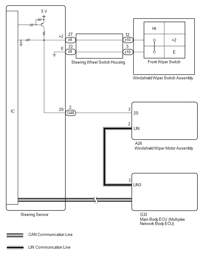
CAUTION / NOTICE / HINT
NOTICE:
Before replacing the main body ECU (multiplex network body ECU), refer to Registration.
Click here 
PROCEDURE
(a) Connect the Techstream to the DLC3.
(b) Turn the engine switch on (IG).
(c) Turn the Techstream on.
(d) Enter the following menus: Body Electrical / Wiper / Trouble Codes.
(e) Clear the DTCs.
Body Electrical > Wiper > Clear DTCs
|
NEXT |
 | |
(a) Connect the Techstream to the DLC3.
(b) Turn the engine switch on (IG).
(c) Move the front wiper switch to the HI position.
(d) Wait 10 seconds or more.
(e) Turn the Techstream on.
(f) Enter the following menus: Body Electrical / Wiper / Trouble Codes.
(g) Check for DTCs.
Body Electrical > Wiper > Trouble Codes
|
Result | Proceed to |
|
DTC B1372 is not output |
A |
| DTC B1372 is output |
B |
| A |
 | USE SIMULATION METHOD TO CHECK |
|
B |
 | |
| 3. |
READ VALUE USING TECHSTREAM |
(a) Connect the Techstream to the DLC3.
(b) Turn the engine switch on (IG).
(c) Turn the Techstream on.
(d) Enter the following menus: Body Electrical / Wiper / Data List.
(e) Read the Data List according to the display on the Techstream.
Body Electrical > Wiper > Data List
|
Tester Display | Measurement Item |
Range | Normal Condition |
Diagnostic Note |
|
Wiper Switch HI (Line) |
Front wiper switch HI position signal (direct line) |
OFF or ON | OFF: Front wiper switch not in HI position
ON: Front wiper switch in HI position |
- |
Body Electrical > Wiper > Data List
|
Tester Display |
| Wiper Switch HI (Line) |
OK:
The Techstream display is normal.
| NG |
 | GO TO STEP 5 |
|
OK |
 | |
| 4. |
READ VALUE USING TECHSTREAM |
(a) Connect the Techstream to the DLC3.
(b) Turn the engine switch on (IG).
(c) Turn the Techstream on.
(d) Enter the following menus: Chassis / Steering Angle Sensor / Data List.
(e) Read the Data List according to the display on the Techstream.
Chassis > Steering Angle Sensor > Data List
|
Tester Display | Measurement Item |
Range | Normal Condition |
Diagnostic Note |
|
Wiper Hi Switch | Front wiper switch HI position signal |
OFF or ON | OFF: Front wiper switch not in HI position
ON: Front wiper switch in HI position |
- |
Chassis > Steering Angle Sensor > Data List
|
Tester Display |
| Wiper Hi Switch |
OK:
The Techstream display is normal.
| OK |
 | REPLACE WINDSHIELD WIPER MOTOR ASSEMBLY |
| NG |
 | REPLACE STEERING SENSOR |
| 5. |
CHECK HARNESS AND CONNECTOR (STEERING SENSOR - WINDSHIELD WIPER MOTOR ASSEMBLY) |
(a) Disconnect the G48 steering sensor connector.
(b) Disconnect the A26 windshield wiper motor assembly connector.
(c) Measure the resistance according to the value(s) in the table below.
Standard Resistance:
|
Tester Connection | Condition |
Specified Condition |
|
G48-2 (2S) - A26-3 (2S) |
Always | Below 1 Ω |
|
G48-2 (2S) or A26-3 (2S) - Body ground |
Always | 10 kΩ Higher |
| NG |
 | REPAIR OR REPLACE HARNESS OR CONNECTOR |
|
OK |
 | |
| 6. |
INSPECT STEERING SENSOR |
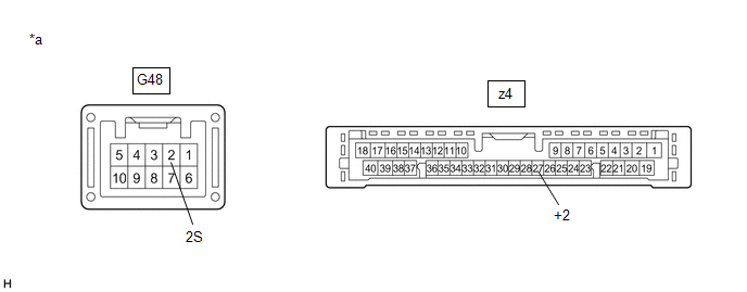
|
*a | Component without harness connected
(Steering Sensor) | - |
- |
(a) Remove the steering sensor.
Click here 
(b) Measure the resistance according to the value(s) in the table below.
Standard Resistance:
|
Tester Connection | Condition |
Specified Condition |
|
G48-2 (2S) - z4-27 (+2) |
Always | Below 1 Ω |
| OK |
 | REPLACE WINDSHIELD WIPER MOTOR ASSEMBLY |
| NG |
 | REPLACE STEERING SENSOR |
Lost Communication with Wiper System LIN BUS (B1373)
DESCRIPTION
The main body
ECU (multiplex network body ECU) and windshield wiper motor assembly
communicate via LIN communication. The main body ECU (multiplex network
body ECU) stores this DTC if communication becomes abnormal.
|
DTC No. | Detection Item |
DTC Detection Condition | Trouble Area |
Memory | DTC Output from |
|
B1373 | Lost Communication with Wiper System LIN BUS |
- Battery voltage is 9.5 V or more
- A malfunction in the communication or LIN communication line between the
main body ECU (multiplex network body ECU) and components of the wiper
system occurs
- 7 seconds or more 3 times consecutively
|
- Windshield wiper motor assembly
- Main body ECU (multiplex network body ECU)
- Harness or connector
| â—‹ |
Main body ECU (multiplex network body ECU) |
WIRING DIAGRAM
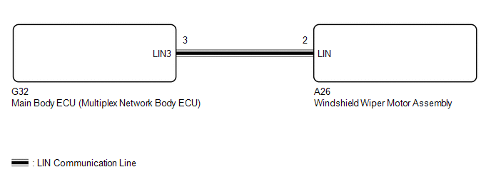
CAUTION / NOTICE / HINT
NOTICE:
Before replacing the main body ECU (multiplex network body ECU), refer to Registration.
Click here 
PROCEDURE
| 1. |
CHECK HARNESS AND CONNECTOR (MAIN BODY ECU (MULTIPLEX NETWORK BODY ECU) - WINDSHIELD WIPER MOTOR ASSEMBLY) |
(a) Disconnect the G32 main body ECU (multiplex network body ECU) connector.
(b) Disconnect the A26 windshield wiper motor assembly connector.
(c) Measure the resistance according to the value(s) in the table below.
Standard Resistance:
|
Tester Connection | Condition |
Specified Condition |
|
G32-3 (LIN3) or A26-2 (LIN) - Body ground |
Always | 10 kΩ Higher |
| NG |
 | REPAIR OR REPLACE HARNESS OR CONNECTOR |
|
OK |
 | |
| 2. |
CHECK MAIN BODY ECU (MULTIPLEX NETWORK BODY ECU) |
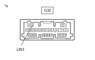
|
*a | Component without harness connected
(Main Body ECU (Multiplex Network Body ECU) |
(a) Check for pulses according to the value(s) in the table below.
Standard Voltage:
|
Tester Connection | Condition |
Specified Condition |
|
G32-3 (LIN3) - Body ground |
Engine switch off | Below 1 V |
|
Engine switch on (IG) |
Pulse generation |
| OK |
 | REPLACE WINDSHIELD WIPER MOTOR ASSEMBLY |
| NG |
 | REPLACE MAIN BODY ECU (MULTIPLEX NETWORK BODY ECU) |
Check For Intermittent Problems
CHECK FOR INTERMITTENT PROBLEMS
NOTICE:
- If the vehicle or vehicle controls are operated (for example, during
initial inspection when the vehicle is brought in for repair) before
operation history has been read and saved, the operation history
information could be lost.
- The Operation History function uses the current system time of the
Techstream and the time counter inside the controlling ECU to calculate
the times shown in the operation history. For this reason, before
reading the operation history, first make sure that the Techstream
system clock is accurately set to the current time.
CHECK OPERATION HISTORY
HINT:
The
windshield wiper motor assembly records the wiper and washer system
operation history, which can be read using the Techstream.
(a) Connect the Techstream to the DLC3.
(b) Turn the engine switch on (IG).
(c) Turn the Techstream on.
(d) Enter the following menus: Body Electrical / Wiper / Utility / Operation History.
Body Electrical > Wiper > Utility
|
Tester Display |
| Operation History |
(e) Following the instructions on the screen, read and save the operation history.
|
Tester Display |
| Motor Lock Detection |
|
Temperature Protection Detection |
|
Overvoltage Detection |
|
Low Voltage Detection |
SYMPTOM SIMULATION
Click here 
Data List / Active Test
DATA LIST / ACTIVE TEST
DATA LIST
NOTICE:
In
the table below, the values listed under "Normal Condition" are
reference values. Do not depend solely on these reference values when
deciding whether a part is faulty or not.
HINT:
Using
the Techstream to read the Data List allows the values or states of
switches, sensors, actuators and other items to be read without removing
any parts. This non-intrusive inspection can be very useful because
intermittent conditions or signals may be discovered before parts or
wiring is disturbed. Reading the Data List information early in
troubleshooting is one way to save diagnostic time.
(a) Connect the Techstream to the DLC3.
(b) Turn the engine switch on (IG).
(c) Turn the Techstream on.
(d) Enter the following menus:
(1) for Wiper: Body Electrical / Wiper / Data List.
(2) for Main Body: Body Electrical / Main Body / Data List.
(3) for Combination Meter: Body Electrical / Combination Meter / Data List.
(4) for Steering Angle Sensor: Chassis / Steering Angle Sensor / Data List.
(e) Read the Data List according to the display on the Techstream.
Body Electrical > Wiper > Data List
|
Tester Display | Measurement Item |
Range | Normal Condition |
Diagnostic Note |
|
Wiper Switch HI (Line) |
Front wiper switch HI position signal (direct line) |
OFF or ON | OFF: Front wiper switch not in HI position
ON: Front wiper switch in HI position |
- |
| Wiper Stop Position |
Windshield wiper motor assembly position |
Store Are/ Lower Rev Pos, Wipe Area or Upper Rev Pos |
Store Are/Lower Rev Pos: Lower reverse position or lower Wipe Area: Between lower reverse position and upper reverse position
Upper Rev Pos: Upper reverse position |
- |
| Wiper Position |
Windshield wiper motor assembly position |
Store Are, Exchange Position or Wipe Area |
Store Are: Out of wiper operating range Exchange Position: Within wiper maintenance position
Wipe Area: Within wiper operating range |
- |
| Status of Motor Lock |
Windshield wiper motor assembly status |
Normal or Lock | Normal: Operating normally
Lock: Malfunctioning |
- |
| Status of Temperature Protection |
Windshield wiper motor assembly temperature protection |
Normal, LO Operation, INT Operation or Stop |
Normal: Windshield wiper motor assembly temperature is below 95°C (203°F)
LO Operation: Windshield wiper motor assembly temperature is 95°C (203°F) or more
INT Operation: Windshield wiper motor assembly temperature is 100°C (212°F) or more
Stop: Windshield wiper motor assembly temperature is 105°C (221°F) or more |
- |
| Status of Overvoltage |
Windshield wiper motor assembly over voltage status |
Normal or Overvoltage | Normal: Operating normally
Overvoltage: Malfunctioning |
- |
| Status of Low Voltage |
Windshield wiper motor assembly low voltage status |
Normal or Low Voltage | Normal: Operating normally
Low voltage: Malfunctioning |
- |
| Motor Shaft Angle |
Windshield wiper motor assembly shaft angle status |
Min.: 0° Max.: 255° |
Almost the same as actual windshield wiper motor assembly shaft angle |
- |
| Motor Temperature |
Windshield wiper motor assembly temperature status |
Min.: -128°C (-198.4°F) Max.: 127°C (260.6°F) |
Almost the same as actual windshield wiper motor assembly temperature |
- |
| Motor Current |
Windshield wiper motor assembly current status |
Min.: 0 A Max.: 63 A |
Almost the same as actual windshield wiper motor assembly current |
- |
| Motor Power Supply Voltage |
Windshield wiper motor assembly voltage status |
Min.: 0 V Max.: 63 V |
Almost the same as actual windshield wiper motor assembly voltage |
- |
| Number of DTCs |
Number of trouble codes |
0 to 255 | Number of stored DTCs displayed |
- |
Body Electrical > Main Body > Data List
|
Tester Display | Measurement Item |
Range | Normal Condition |
Diagnostic Note |
|
Communication Wiper ECU |
Connection status between windshield wiper motor assembly and main body ECU (multiplex network body ECU) |
STOP or OK | STOP: Not Connected
OK: Connected | DTCs are stored if a malfunction occurs in the CAN communication system. |
|
Communication Humidity/Rain Sensor |
Connection status between rain sensor and main body ECU (multiplex network body ECU) |
STOP or OK | STOP: Not Connected
OK: Connected | Although this item is displayed on the Techstream, it is not applicable to this vehicle. |
|
The Number of DTC | Number of trouble codes |
0 to 255 | Number of stored DTCs displayed |
- |
Body Electrical > Combination Meter > Data List
|
Tester Display | Measurement Item |
Range | Normal Condition |
Diagnostic Note |
|
Washer Level Warning Switch |
Washer fluid level warning switch |
OFF or ON | OFF: Washer fluid level not low
ON: Washer fluid level low |
- |
Chassis > Steering Angle Sensor > Data List
|
Tester Display | Measurement Item |
Range | Normal Condition |
Diagnostic Note |
|
Wiper OFF Switch | Front wiper switch OFF position signal |
OFF or ON | OFF: Front wiper switch not in OFF position
ON: Front wiper switch in OFF position |
- |
| Wiper Auto/Int Switch |
Front wiper switch INT position signal |
OFF or ON | OFF: Front wiper switch not in INT position
ON: Front wiper switch in INT position |
- |
| Wiper Lo Switch |
Front wiper switch LO position signal |
OFF or ON | OFF: Front wiper switch not in LO position
ON: Front wiper switch in LO position |
- |
| Wiper Hi Switch |
Front wiper switch HI position signal |
OFF or ON | OFF: Front wiper switch not in HI position
ON: Front wiper switch in HI position |
- |
| Wiper Mist Switch |
Front wiper switch MIST position signal |
OFF or ON | OFF: Front wiper switch not in MIST position
ON: Front wiper switch in MIST position |
- |
| Washer Switch |
Washer switch ON position signal |
OFF or ON | OFF: Front washer switch not in ON position
ON: Front washer switch in ON position |
- |
| Rear Wiper Lo Switch |
Rear wiper switch LO position signal |
OFF or ON | OFF: Rear wiper switch not in LO position
ON: Rear wiper switch in LO position |
Although this item is displayed on the Techstream, it is not applicable to this vehicle. |
|
Rear Wiper Hi Switch | Rear wiper switch HI position signal |
OFF or ON | OFF: Rear wiper switch not in HI position
ON: Rear wiper switch in HI position |
Although this item is displayed on the Techstream, it is not applicable to this vehicle. |
|
Rear Washer Switch | Rear washer switch ON position signal |
OFF or ON | OFF: Rear washer switch not in ON position
ON: Rear washer switch in ON position |
Although this item is displayed on the Techstream, it is not applicable to this vehicle. |
|
Intermittent Time Volume |
Intermittent time adjustment switch condition |
Shortest, Shorter, Longer or Longest |
Shortest: P4 Shorter: P3 Longer: P2 Longest: P1 |
* |
| Wiper Spec Info |
Function information |
Unknown, Auto spec or INT spec |
Unknown: Specification not stored Auto spec: w/ Auto wiper system
INT spec: w/o Auto wiper system |
- |
| The Number of DTCs |
Number of trouble codes |
0 to 255 | Number of stored DTCs displayed |
- |
- *: Refer to Inspection for each position of the switch.
Click here 
ACTIVE TEST
HINT:
Using
the Techstream to perform Active Tests allows relays, VSVs, actuators
and other items to be operated without removing any parts. This
non-intrusive functional inspection can be very useful because
intermittent operation may be discovered before parts or wiring is
disturbed. Performing Active Tests early in troubleshooting is one way
to save diagnostic time. Data List information can be displayed while
performing Active Tests.
(a) Connect the Techstream to the DLC3.
(b) Turn the engine switch on (IG).
(c) Turn the Techstream on.
(d) Enter the following menus:
(1) for Wiper: Body Electrical / Wiper / Active Test.
(2) for Main Body: Body Electrical / Main Body / Active Test.
(e) Perform the Active Test according to the display on the Techstream.
Body Electrical > Wiper > Active Test
|
Tester Display | Measurement Item |
Control Range | Diagnostic Note |
|
Wiper Motor LO | Function to operate the windshield wiper motor assembly in LO |
OFF or ON | - |
|
Wiper Motor HI | Function to operate the windshield wiper motor assembly in HI |
OFF or ON | - |
Body Electrical > Main Body > Active Test
|
Tester Display | Measurement Item |
Control Range | Diagnostic Note |
|
Washer Nozzle Heater | Function to operate the nozzle heater |
OFF or ON | Although this item is displayed on the Techstream, it is not applicable to this vehicle. |
|
Wiper Power Relay | Function to operate the WIPER relay |
OFF or ON | - |
|
Front Washer Relay | Function to operate the windshield washer motor and pump assembly |
OFF or ON | - |
Diagnostic Trouble Code Chart
DIAGNOSTIC TROUBLE CODE CHART
Wiper and Washer System |
DTC No. | Detection Item |
DTC Output from | Link |
|
B1245 | Lost Communication with Wiper ECU LIN |
Main body ECU (multiplex network body ECU) |
 |
|
B1370 | ECU Malfunction |
Windshield wiper motor assembly |
 |
|
B1372 | Wiper Switch Signal Mismatch between LIN and Line |
Windshield wiper motor assembly |
 |
|
B1373 | Lost Communication with Wiper System LIN BUS |
Main body ECU (multiplex network body ECU) |
 |
Dtc Check / Clear
DTC CHECK / CLEAR
CHECK FOR DTC
(a) Connect the Techstream to the DLC3.
(b) Turn the engine switch on (IG).
(c) Turn the Techstream on.
(d) Enter the following menus: Body Electrical / (desired system) / Trouble Codes.
Body Electrical > Wiper > Trouble Codes Body Electrical > Main Body > Trouble Codes
(e) Check for DTCs.
CLEAR DTC
(a) Connect the Techstream to the DLC3.
(b) Turn the engine switch on (IG).
(c) Turn the Techstream on.
(d) Enter the following menus: Body Electrical / (desired system) / Trouble Codes.
Body Electrical > Wiper > Clear DTCs Body Electrical > Main Body > Clear DTCs
(e) Clear the DTCs.
Fail-safe Chart
FAIL-SAFE CHART
PROTECTION FUNCTION
(a)
The windshield wiper motor assembly operates the following protection
functions if it detects an abnormal condition, in order to protect the
wiper and washer system.
|
Item | Protection Content |
Conditions to Return to Normal Condition |
|
Overheat protection | Decreases
wiper operating speed in order to protect the windshield wiper motor
assembly if the windshield wiper motor assembly temperature becomes
excessively high.
- Prohibits wiper operation in HI when the windshield wiper motor assembly temperature is 95°C (203°F) or higher.
- Prohibits wiper operation in LO and HI when the windshield wiper motor assembly temperature is 100°C (212°F) or higher.
- Prohibits wiper operation when the windshield wiper motor assembly temperature is 105°C (221°F) or higher.
| The windshield wiper motor assembly returns to normal. |
|
Snow protection | Reverses
the direction of the wipers and decreases their operating range when an
excessive load, due to snow, etc., is detected near the extremities of
the wiper operating range. In this case, operation
is stopped at the lower reverse position for a certain period of time to
prevent the windshield wiper motor assembly from overheating. |
Foreign matter, such as snow, is removed and the wiper operating range returns to normal. |
|
Excessive load protection | Stops wiper operation when an excessive load is detected when the wipers are near the center of the operating range. |
The front wiper switch is turned off and then to any operating position. |
Freeze Frame Data
FREEZE FRAME DATA
FREEZE FRAME DATA
(a) Whenever a DTC is detected, the windshield wiper motor assembly stores the current vehicle state as Freeze Frame Data.
CHECK FREEZE FRAME DATA
(a) Connect the Techstream to the DLC3.
(b) Turn the engine switch on (IG).
(c) Turn the Techstream on.
(d) Enter the following menus: Body Electrical / Wiper / Trouble Codes.
Body Electrical > Wiper > Trouble Codes Body Electrical > Wiper
|
Tester Display | Measurement Item |
Range | Normal Condition |
Diagnostic Note |
|
Wiper Switch HI (Line) |
Front wiper switch HI position signal (direct line) |
OFF or ON | OFF: Front wiper switch not in HI position
ON: Front wiper switch in HI position |
- |
| Wiper Stop Position |
Windshield wiper motor assembly position |
Store Are/Lower Rev Pos, Wipe Area or Upper Rev Pos |
Store Are/Lower Rev Pos: Lower reverse position or lower Wipe Area: Between lower reverse position and upper reverse position
Upper Rev Pos: Upper reverse position |
- |
| Wiper Position |
Windshield wiper motor assembly position |
Store Are, Exchange Position or Wipe Area |
Store Are: Out of wiper operating range Exchange Position: Within wiper maintenance position
Wipe Area: Within wiper operating range |
- |
| Status of Motor Lock |
Windshield wiper motor assembly status |
Normal or Lock | Normal: Operating normally
Lock: Malfunctioning |
- |
| Status of Temperature Protection |
Windshield wiper motor assembly temperature protection |
Normal, LO Operation, INT Operation or Stop |
Normal: Windshield wiper motor assembly temperature is below 95°C (203°F)
LO Operation: Windshield wiper motor assembly temperature is 95°C (203°F) or more
INT Operation: Windshield wiper motor assembly temperature is 100°C (212°F) or more
Stop: Windshield wiper motor assembly temperature is 105°C (221°F) or more |
- |
| Status of Overvoltage |
Windshield wiper motor assembly over voltage status |
Normal or Overvoltage | Normal: Operating normally
Overvoltage: Malfunctioning |
- |
| Status of Low Voltage |
Windshield wiper motor assembly low voltage status |
Normal or Low Voltage | Normal: Operating normally
Low voltage: Malfunctioning |
- |
| Motor Shaft Angle |
Windshield wiper motor assembly shaft angle status |
Min.: 0° Max.: 255° |
Almost the same as actual windshield wiper motor assembly shaft angle |
- |
| Motor Temperature |
Windshield wiper motor assembly temperature status |
Min.: -128°C (-198.4°F) Max.: 127°C (260.6°F) |
Almost the same as actual windshield wiper motor assembly temperature |
- |
| Motor Current |
Windshield wiper motor assembly current status |
Min.: 0 A Max.: 63 A |
Almost the same as actual windshield wiper motor assembly current |
- |
| Motor Power Supply Voltage |
Windshield wiper motor assembly voltage status |
Min.: 0 V Max.: 63 V |
Almost the same as actual windshield wiper motor assembly voltage |
- |
| Number of DTCs |
Number of trouble codes |
0 to 255 | Number of stored DTCs displayed |
- |
How To Proceed With Troubleshooting
CAUTION / NOTICE / HINT
HINT:
- Use the following procedure to troubleshoot the wiper and washer system.
PROCEDURE
|
1. | VEHICLE BROUGHT TO WORKSHOP |
|
NEXT |
 | |
| 2. |
CUSTOMER PROBLEM ANALYSIS |
HINT:
- In troubleshooting, confirm that the problem symptoms have been
accurately identified. Preconceptions should be discarded in order to
make an accurate judgment. To clearly understand what the problem
symptoms are, it is extremely important to ask the customer about the
problem and the conditions at the time the malfunction occurred.
- Gather as much information as possible for reference. Past problems that seem unrelated may also help in some cases.
- The following 5 items are important points for problem analysis:
|
What |
Vehicle model, system name |
|
When |
Date, time, occurrence frequency |
|
Where |
Road conditions |
|
Under what conditions? |
Driving conditions, weather conditions |
|
How did it happen? |
Problem symptoms |
|
NEXT |
 | |
| 3. |
READ OUT AND SAVE OPERATION HISTORY |
NOTICE:
- If the vehicle or vehicle controls are operated (for example, during
initial inspection when the vehicle is brought in for repair) before
operation history has been read out and saved, the operation history
information could be lost.
- The function "Read operation history" uses the current system time
setting inside the Techstream and the time counter inside the
controlling ECU to calculate the timings shown in the operation history.
For this reason, before reading out the operation history, first make
sure that the Techstream system clock is accurately set to the current
time.
(a) Read out and save operation history using the Techstream.
Click here

Body Electrical > Wiper > Utility
|
Tester Display |
| Operation History |
|
NEXT |
 | |
(a) Measure the battery voltage with engine switch off.
Standard Voltage:
11 to 14 V
If the voltage is below 11 V, recharge or replace the battery before proceeding to the next step.
(b) Check the fuses and relays.
(c)
Check the connector connections and terminals to make sure that there
are no abnormalities such as loose connections, deformation, etc.
|
NEXT |
 | |
| 5. |
CHECK COMMUNICATION FUNCTION OF CAN COMMUNICATION SYSTEM* |
(a) Using the Techstream, check for CAN communication system DTCs.
Click here

|
Result | Proceed to |
|
CAN DTCs are not output |
A |
| CAN DTCs are output |
B |
| B |
 | GO TO CAN COMMUNICATION SYSTEM |
|
A |
 | |
(a) Check for DTCs.
Body Electrical > Wiper > Trouble Codes Body Electrical > Main Body > Trouble Codes
|
Result | Proceed to |
|
DTCs are not output | A |
|
DTCs are output | B |
| B |
 | GO TO DIAGNOSTIC TROUBLE CODE CHART |
|
A |
 | |
| 7. |
PROBLEM SYMPTOMS TABLE |
(a) Refer to Problem Symptoms Table.
Click here 
|
Result | Proceed to |
|
Fault is not listed in Problem Symptoms Table |
A |
| Fault is listed in Problem Symptoms Table |
B |
| B |
 | GO TO PROBLEM SYMPTOMS TABLE |
|
A |
 | |
| 8. |
OVERALL ANALYSIS AND TROUBLESHOOTING* |
(a) Operation Check.
Click here 
(b) Data List / Active Test
Click here 
(c) Terminals of ECU
Click here 
(d) Fail-safe Chart
Click here 
(e) Inspection
(f) On-vehicle inspection
|
NEXT |
 | |
| 9. |
ADJUST, REPAIR OR REPLACE |
|
NEXT |
 | |
| NEXT |
 | END |
Operation Check
OPERATION CHECK
CHECK SERVICE POSITION CONTROL
(a) Turn the engine switch off.
(b)
Within approximately 45 seconds of turning the engine switch off, hold
the windshield wiper switch assembly in the MIST position for 2 seconds
and confirm that the wipers move to the uppermost position.
CHECK VEHICLE SPEED SENSING TYPE ADJUSTABLE INTERMITTENT WIPER CONTROL
(a) Turn the engine switch on (IG).
(b) Move the windshield wiper switch assembly to the INT position.
(c)
Check that the intermittent operation interval changes between
approximately 1.5 to 11 seconds according to the vehicle speed and the
position of the intermittent time adjustment switch of the windshield
wiper switch assembly.
CHECK INTERMITTENT CONTROL FUNCTION
(a) Turn the engine switch on (IG).
(b) Move the windshield wiper switch assembly to the INT position.
(c)
Check that the intermittent operation interval can be adjusted between
approximately 4 to 12.5 seconds by operating the intermittent time
adjustment switch.
WASHER OPERATION INSPECTION
(a) Turn the engine switch on (IG).
(b) Check washer cooperation:
Operate
the washer switch for approximately 0.5 seconds or more and check that
the front wipers operate in LO and washer fluid is sprayed. Then release
the washer switch and check that the front wipers operate for 3 cycles.
(c) Drip prevention wiper function:
With
the vehicle speed less than approximately 5 km/h (3 mph), operate the
washer switch and check that the front wipers operate for 1 cycle
approximately 3 seconds after washer cooperation completes.
CHECK WASHER FLUID LEVEL LOW WARNING
(a)
Check that when the volume of washer fluid decreases to below a certain
level (the level warning switch turns on), a warning message is
displayed on the multi-information display.
Parts Location
PARTS LOCATION
ILLUSTRATION
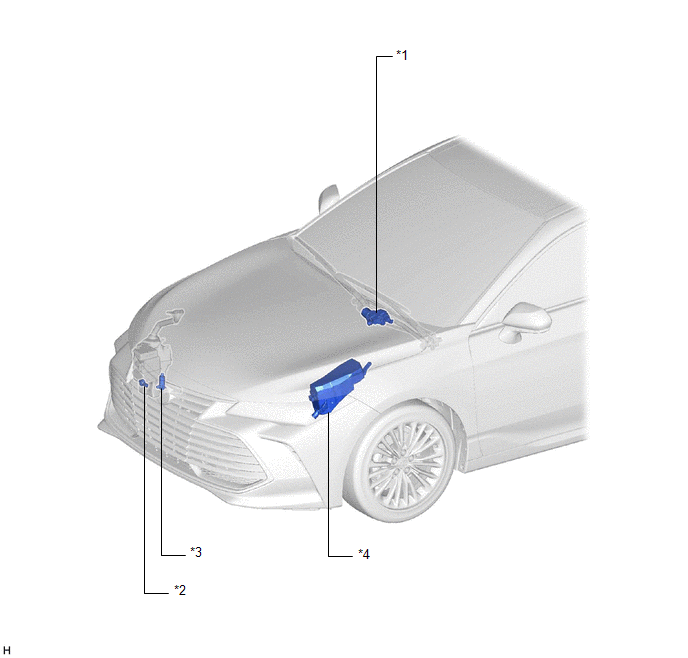
|
*1 | WINDSHIELD WIPER MOTOR ASSEMBLY |
*2 | LEVEL WARNING SWITCH ASSEMBLY |
|
*3 | WINDSHIELD WASHER MOTOR AND PUMP ASSEMBLY |
*4 | NO. 1 ENGINE ROOM RELAY BLOCK AND NO. 1 JUNCTION BLOCK ASSEMBLY
- WIPER FUSE - WIPER RELAY - WASHER RELAY |
ILLUSTRATION
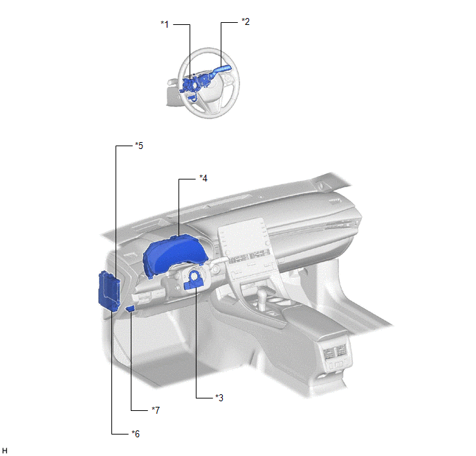
|
*1 | STEERING WHEEL SWITCH HOUSING |
*2 | WINDSHIELD WIPER SWITCH ASSEMBLY |
|
*3 | STEERING SENSOR |
*4 | COMBINATION METER ASSEMBLY |
|
*5 | MAIN BODY ECU (MULTIPLEX NETWORK BODY ECU) |
*6 | INSTRUMENT PANEL JUNCTION BLOCK ASSEMBLY
- WASHER FUSE |
|
*7 | DLC3 |
- | - |
Precaution
PRECAUTION
PRECAUTION FOR DISCONNECTING CABLE FROM NEGATIVE BATTERY TERMINAL
NOTICE:
When
disconnecting the cable from the negative (-) battery terminal,
initialize the following systems after the cable is reconnected.
|
System Name | See Procedure |
|
Lane Departure Alert System (w/ Steering Control) |
 |
|
Intelligent Clearance Sonar System |
|
Parking Assist Monitor System |
|
Panoramic View Monitor System |
|
Pre-collision System |
|
Lighting System (for Gasoline Model with Cornering Light) |
PRECAUTION FOR WASHER NOZZLE ADJUSTMENT
(a) Do not clean or adjust the washer nozzle with a safety pin, etc. because:
(1) The washer nozzle tip is made of resin and may be damaged.
(2)
Adjustment is not necessary for this spray type washer nozzle. If it is
necessary to change the nozzle angle, replace the washer nozzle with
one that has a different nozzle angle.
Click here

(b)
If the washer nozzle is clogged with wax, etc., remove it and clean the
nozzle hole with a soft resin brush or other cleaning tool.
Problem Symptoms Table
PROBLEM SYMPTOMS TABLE
NOTICE:
Before replacing the main body ECU (multiplex network body ECU), refer to Registration.
Click here 
HINT:
- Use the table below to help determine the cause of problem symptoms. If
multiple suspected areas are listed, the potential causes of the
symptoms are listed in order of probability in the "Suspected Area"
column of the table. Check each symptom by checking the suspected areas
in the order they are listed. Replace parts as necessary.
- Inspect the fuses and relays related to this system before inspecting the suspected areas below.
Front Wiper and Washer System |
Symptom | Suspected Area |
Link |
|
Front wipers do not operate at all |
Proceed to "Wiper and Washer Switch Circuit" |
 |
|
Windshield wiper motor assembly |
 |
|
Front wipers do not operate in INT |
Proceed to "Wiper and Washer Switch Circuit" |
 |
|
Front wipers do not operate in LO |
Proceed to "Wiper and Washer Switch Circuit" |
 |
|
Front wipers do not operate in HI |
Proceed to "Wiper and Washer Switch Circuit" |
 |
|
Front wipers do not operate in MIST |
Proceed to "Wiper and Washer Switch Circuit" |
 |
|
When
the wiper switch is in the INT position, the front wiper intermittent
operation interval cannot be adjusted by the intermittent time
adjustment switch | Proceed to "Wiper and Washer Switch Circuit" |
 |
|
Windshield wiper motor assembly |
 |
|
When
the front wipers are operating in INT, the front wiper intermittent
operation interval does not change according to changes in the vehicle
speed | Windshield wiper motor assembly |
 |
|
Front wipers continuously operate in LO |
Proceed to "Wiper and Washer Switch Circuit" |
 |
|
Front wipers continuously operate in HI |
Proceed to "Wiper and Washer Switch Circuit" |
 |
|
Front wipers continuously operate in INT |
Windshield wiper motor assembly |
 |
|
"Wiper System Malfunction Visit Your Dealer" is displayed on the multi-information display |
Windshield wiper motor assembly |
 |
|
Main body ECU (Multiplex network body ECU) |
 |
|
Combination meter assembly |
 |
|
Front wipers do not move to the service position (wiper operation is normal) |
Main body ECU (Multiplex network body ECU) |
 |
|
Windshield washer motor and pump assembly does not operate |
Proceed to "Washer Motor Circuit" |
 |
|
Proceed to "Wiper and Washer Switch Circuit" |
 |
|
Washer fluid does not flow (Windshield washer motor and pump assembly is normal) |
Washer fluid | - |
|
Washer hose and nozzle |
- |
| When the front wiper switch is turned off, the front wipers do not move to the park position or stop in the wrong position |
Check the automatic stop (park) position |
 |
|
Main body ECU (Multiplex network body ECU) |
 |
|
Front wipers did not operate before, but operate now |
Check the Operation History |
 |
Washer Fluid Level Warning System |
Symptom | Suspected Area |
Link |
| "Windshield Washer Fluid Low" is displayed on the multi-information display when washer fluid level is not low |
Proceed to "Washer Fluid Level Warning Switch Circuit" |
 |
|
"Windshield Washer Fluid Low" is not displayed on the multi-information display when washer fluid level is low |
Washer fluid | - |
|
Proceed to "Washer Fluid Level Warning Switch Circuit" |
 |
System Description
SYSTEM DESCRIPTION
FRONT WIPER AND WASHER CONTROL FUNCTION
|
Control/Function | Description |
|
Wiper speed regulation | Maintains the default speed of the wipers even when the supply voltage or resistance changes. |
|
Wiper speed HI to LO transition control |
Smoothly controls the change in speed of the wipers when the wiper speed is changed from HI to LO. |
|
Service position control | Stops
the front wipers at the top of their stroke when the windshield wiper
switch assembly is held in the MIST position for 2 seconds or more
within approximately 45 seconds after the engine switch is turned off.
HINT:
- The front wipers can be returned from the service position by turning
the engine switch on (IG) and operating the windshield wiper switch
assembly.
- If the MIST function is operated when the front wipers are in the
service position, the front wipers will return to the park position.
- The front wipers must be in the service position when locking them back*.
|
| Engine hood interference damage reduction function |
- Operates the windshield wiper motor assembly at a slow speed for the
first cycle when returning from the service position to minimize damage
to the engine hood if a wiper arm is still in the lock-back position.
- Moves the wipers a short distance in reverse if a wiper arm in the
lock-back position contacts the engine hood and the windshield wiper
motor locks up.
|
| Self-locking control |
Holds the wipers in the park position when the engine switch is on (IG). |
|
Protection mode |
- Limits the operation of the windshield wiper motor assembly when
excessive load is detected, in order to protect the wiper and washer
system.
- Refer to Fail-safe chart.
Click here 
|
| MIST function |
Operates the wipers in LO when the windshield wiper switch assembly is held in the MIST position. |
|
Vehicle speed sensing type adjustable intermittent wiper control |
Controls the delay of the front wipers when the windshield wiper switch assembly is in the INT position.
HINT:
- The intermittent operation interval is controlled by the intermittent
time adjustment switch of the windshield wiper switch assembly.
- The intermittent operation interval of delay changes in accordance with the vehicle speed.
- When the windshield wiper switch assembly is in the INT position and the
vehicle is stopped, the wipers operate for 1 cycle when the vehicle
starts off.
- When the intermittent time adjustment switch is moved to a faster
position, the delay is reset and control begins according to the new
setting.
|
| Washer cooperation |
- When the washer switch is operated for 0.5 seconds or more, the front wipers operate in LO.
- When the washer switch is released, the front wipers operate in LO for 3 additional cycles.
NOTICE: If the
washer switch is operated for approximately 40 seconds or more,
operation of the windshield washer motor and pump assembly is stopped to
prevent burnout, and the front wipers are returned to the park
position. |
| Drip prevention wiper function |
Approximately
3 seconds after washer cooperation completes, operates the front wipers
for 1 cycle to remove any remaining washer fluid. HINT: This
function only operates when the vehicle is stationary and will stop
operating at a vehicle speed of approximately 5 km/h (3 mph) or more. |
|
Vehicle stopped wiper control | If
the vehicle is stopped and the windshield wiper switch assembly is
moved to the LO position, the front wipers will operate in LO for 3
cycles and then at a 2.5 second interval. |
- *: Function that allows the front wiper arms to be folded back such as when replacing the wiper rubber.
OTHER FUNCTIONS
|
Control/Function | Description |
|
Washer fluid level low warning | Displays
"Windshield Washer Fluid Low" on the multi-information display in the
combination meter assembly when the washer fluid level is low. |
|
Wiper system warning | Displays
"Wiper System Malfunction Visit Your Dealer" on the multi-information
display in the combination meter assembly when the wiper and washer
system is malfunctioning. |
System Diagram
SYSTEM DIAGRAM
FRONT WIPER AND WASHER SYSTEM
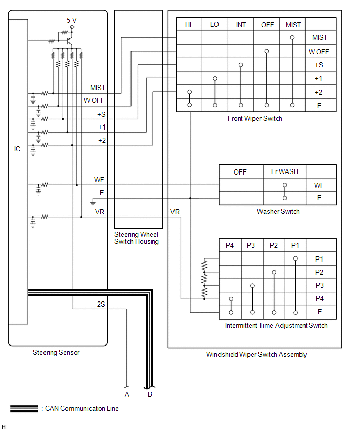
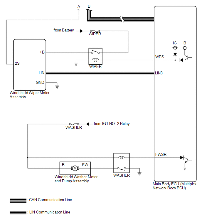
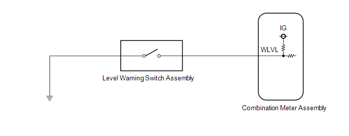
WASHER FLUID LEVEL WARNING SYSTEM
Terminals Of Ecu
TERMINALS OF ECU
CHECK WINDSHIELD WIPER MOTOR ASSEMBLY

(a) Disconnect the A26 windshield wiper motor assembly connector.
(b) Measure the voltage and resistance on the wire harness side connector according to the value(s) in the table below.
|
Terminal No. (Symbol) |
Wiring Color | Terminal Description |
Condition | Specified Condition |
|
A26-1 (GND) - Body ground |
W-B - Body ground | Ground |
Always | Below 1 Ω |
|
A26-4 (+B) - Body ground |
SB - Body ground |
Engine switch on (IG) signal (Power source circuit) |
Engine switch on (IG) |
11 to 14 V |
|
Less than approximately 60 seconds after engine switch turned off |
|
Approximately 60 seconds or more after engine switch turned off |
Below 1 V |
(c) Connect the A26 windshield wiper motor assembly connector.
HINT:
Since
the A26 windshield wiper motor assembly connector is a waterproof type
connector, the voltage and pulses cannot be checked directly. The values
listed are for reference only.
(d) Measure the voltage and check for pulses according to the value(s) in the table below.
|
Terminal No. (Symbol) |
Wiring Color | Terminal Description |
Condition | Specified Condition |
|
A26-2 (LIN) - Body ground |
R - Body ground | LIN communication signal |
Engine switch on (IG) |
Pulse generation |
|
A26-3 (2S) - Body ground |
B - Body ground |
Windshield wiper motor assembly HI operation signal |
Windshield wiper motor assembly stopped |
4.8 to 5.2 V |
|
Windshield wiper motor assembly operating in HI |
Below 1 V |
CHECK MAIN BODY ECU (MULTIPLEX NETWORK BODY ECU) AND INSTRUMENT PANEL JUNCTION BLOCK ASSEMBLY
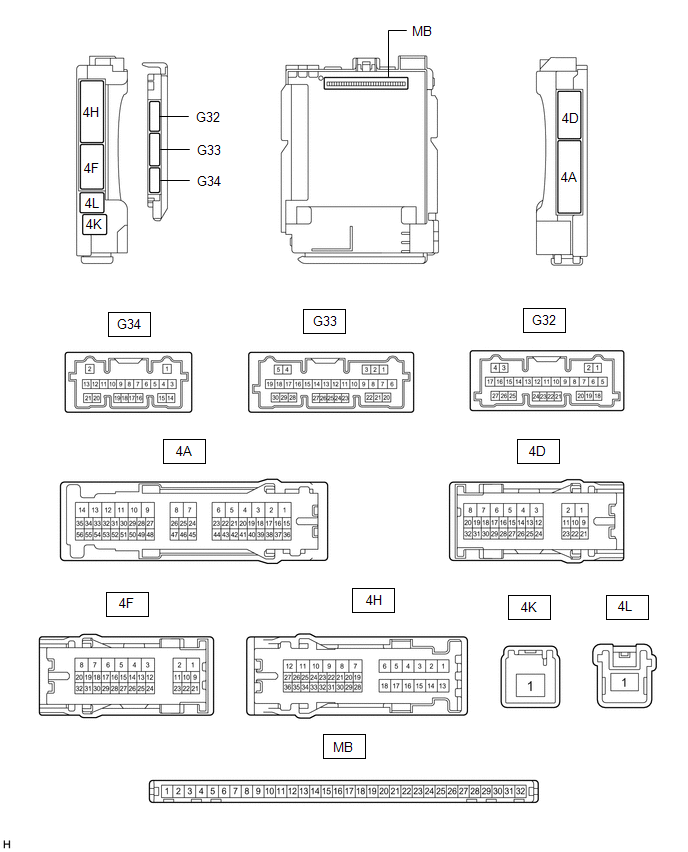
(a) Disconnect the instrument panel junction block assembly and main body ECU (multiplex network body ECU) connectors.
(b) Measure the voltage and resistance according to the value(s) in the table below.
|
Terminal No. (Symbol) | Wiring Color |
Terminal Description | Condition |
Specified Condition |
|
4D-3 - Body ground | LA - Body ground |
Ground | Always |
Below 1 Ω |
|
4F-1 - Body ground | LG - Body ground |
Battery power supply |
Always | 11 to 14 V |
|
4K-1 - Body ground | W - Body ground |
Battery power supply |
Always | 11 to 14 V |
(c) Connect the instrument panel junction block assembly and main body ECU (multiplex network body ECU) connectors.
(d) Measure the voltage and check for pulses according to the value(s) in the table below.
|
Terminal No. (Symbol) | Wiring Color |
Terminal Description | Condition |
Specified Condition |
|
4F-2 - Body ground | R - Body ground |
Washer circuit IG power source |
Engine switch on (IG) |
11 to 14 V |
|
G32-3 (LIN3) - Body ground |
BE - Body ground | LIN communication line |
Engine switch on (IG) |
Pulse generation |
|
G32-12 (FWSR) - Body ground |
L - Body ground |
WASHER Relay operation signal |
Engine switch on (IG), front washer switch off |
11 to 14 V |
|
Engine switch on (IG), front washer switch on |
Below 2 V |
|
G33-21 (WPS) - Body ground |
LG - Body ground |
WIPER Relay operation signal |
Engine switch on (IG) |
11 to 14 V |
|
Less than approximately 60 seconds after engine switch turned off |
|
Approximately 60 seconds or more after engine switch turned off |
Below 1 V |
CHECK COMBINATION METER ASSEMBLY
Click here 
Utility
UTILITY
OPERATION HISTORY
HINT:
History
of Reason for Operation: The windshield wiper motor assembly stores
Operation History which can be read using the Techstream, when a
malfunction of the wiper and washer system occurs.
Click here

(a) Connect the Techstream to the DLC3.
(b) Turn the engine switch on (IG).
(c) Turn the Techstream on.
(d) Enter the following menus: Body Electrical / Wiper / Utility.
(e) Following the instructions on the screen, save the operation history.
Body Electrical > Wiper > Utility
|
Tester Display |
| Operation History |
WIPER SPECIFICATION SWITCH
HINT:
This item is displayed on the Techstream, but cannot be operated as the auto wiper system is not available for this vehicle.
(a) Connect the Techstream to the DLC3.
(b) Turn the engine switch on (IG).
(c) Turn the Techstream on.
(d) Enter the following menus: Chassis / Steering Angle Sensor / Utility.
(e) According to the display on the Techstream, select Wiper Specification Switch.
Chassis > Steering Angle Sensor > Utility
|
Tester Display |
| Wiper Specification Switch |
Washer Fluid Level Warning Switch Circuit
DESCRIPTION
When the washer fluid level is lower than a certain level, a warning message is displayed on the combination meter assembly.
WIRING DIAGRAM
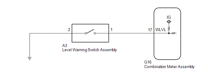
PROCEDURE
| 1. |
READ VALUE USING TECHSTREAM |
(a) Connect the Techstream to the DLC3.
(b) Turn the engine switch on (IG).
(c) Turn the Techstream on.
(d) Enter the following menus: Body Electrical / Combination Meter / Data List.
(e) Read the Data List according to the display on the Techstream.
Body Electrical > Combination Meter > Data List
|
Tester Display | Measurement Item |
Range | Normal Condition |
Diagnostic Note |
|
Washer Level Warning Switch |
Washer fluid level warning switch |
OFF or ON | OFF: Washer fluid level not low
ON: Washer fluid level low |
- |
Body Electrical > Combination Meter > Data List
|
Tester Display |
| Washer Level Warning Switch |
OK:
The Techstream display changes correctly in response to the washer fluid level.
| OK |
 | REPLACE COMBINATION METER ASSEMBLY |
|
NG |
 | |
| 2. |
INSPECT LEVEL WARNING SWITCH ASSEMBLY |
(a) Remove the level warning switch assembly.
Click here

(b) Inspect the level warning switch assembly.
Click here 
| NG |
 | REPLACE LEVEL WARNING SWITCH ASSEMBLY |
|
OK |
 | |
| 3. |
CHECK HARNESS AND CONNECTOR (LEVEL WARNING SWITCH ASSEMBLY - COMBINATION METER ASSEMBLY) |
(a) Disconnect the G16 combination meter assembly connector.
(b) Measure the resistance according to the value(s) in the table below.
Standard Resistance:
|
Tester Connection | Condition |
Specified Condition |
|
A3-1 - G16-17 (WLVL) |
Always | Below 1 Ω |
|
A3-1 or G16-17 (WLVL) - Body ground |
Always | 10 kΩ or higher |
| NG |
 | REPAIR OR REPLACE HARNESS OR CONNECTOR |
|
OK |
 | |
| 4. |
CHECK HARNESS AND CONNECTOR (LEVEL WARNING SWITCH ASSEMBLY - BODY GROUND) |
(a) Measure the resistance according to the value(s) in the table below.
Standard Resistance:
|
Tester Connection | Condition |
Specified Condition |
|
A3-2 - Body ground | Always |
Below 1 Ω |
| OK |
 | REPLACE COMBINATION METER ASSEMBLY |
| NG |
 | REPAIR OR REPLACE HARNESS OR CONNECTOR |
Washer Motor Circuit
DESCRIPTION
When the
windshield washer motor and pump assembly receives signals from the
windshield wiper switch assembly, it operates to spray washer fluid from
the washer nozzle sub-assemblies.
WIRING DIAGRAM
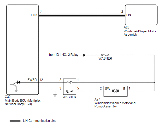
CAUTION / NOTICE / HINT
NOTICE:
- Inspect the fuses for circuits related to this system before performing the following procedure.
- Before replacing the main body ECU (multiplex network body ECU), refer to Registration.
Click here 
PROCEDURE
|
1. | PERFORM ACTIVE TEST USING TECHSTREAM |
(a) Connect the Techstream to the DLC3.
(b) Turn the engine switch on (IG).
(c) Turn the Techstream on.
(d) Enter following menus: Body Electrical / Main Body / Active Test.
(e) Perform the Active Test according to the display on the Techstream.
Body Electrical > Main Body > Active Test
|
Tester Display | Measurement Item |
Control Range | Diagnostic Note |
|
Front Washer Relay | Function to operate the windshield washer motor and pump assembly |
OFF or ON | - |
Body Electrical > Main Body > Active Test
|
Tester Display |
| Front Washer Relay |
OK:
Windshield washer motor and pump assembly operates normally.
| OK |
 | PROCEED TO NEXT SUSPECTED AREA SHOWN IN PROBLEM SYMPTOMS TABLE |
|
NG |
 | |
| 2. |
INSPECT WINDSHIELD WASHER MOTOR AND PUMP ASSEMBLY |
(a) Remove the windshield washer motor and pump assembly.
Click here

(b) Inspect the windshield washer motor and pump assembly.
Click here 
| NG |
 | REPLACE WINDSHIELD WASHER MOTOR AND PUMP ASSEMBLY |
|
OK |
 | |
(a) Inspect the WASHER relay.
Click here 
| NG |
 | REPLACE WASHER RELAY |
|
OK |
 | |
| 4. |
CHECK HARNESS AND CONNECTOR (POWER SOURCE - WASHER RELAY) |
(a) Measure the voltage according to the value(s) in the table below.
Standard Voltage:
|
Tester Connection | Condition |
Specified Condition |
|
1 (WASHER relay) - Body ground |
Engine switch off | Below 1 V |
|
Engine switch on (IG) |
11 to 14 V |
| NG |
 | REPAIR OR REPLACE HARNESS OR CONNECTOR |
|
OK |
 | |
| 5. |
CHECK HARNESS AND CONNECTOR (POWER SOURCE - WINDSHIELD WASHER MOTOR AND PUMP ASSEMBLY) |
(a) Measure the voltage according to the value(s) in the table below.
Standard Voltage:
|
Tester Connection | Condition |
Specified Condition |
|
A27-1 (B) - Body ground |
Engine switch off | Below 1 V |
|
Engine switch on (IG) |
11 to 14 V |
| NG |
 | REPAIR OR REPLACE HARNESS OR CONNECTOR |
|
OK |
 | |
| 6. |
CHECK HARNESS AND CONNECTOR (WASHER RELAY - WINDSHIELD WASHER MOTOR AND PUMP ASSEMBLY) |
(a) Measure the resistance according to the value(s) in the table below.
Standard Resistance:
|
Tester Connection | Condition |
Specified Condition |
|
5 (WASHER relay) - A27-2 (SW) |
Always | Below 1 Ω |
|
5 (WASHER relay) or A27-2 (SW) - Body ground |
Always | 10 kΩ or higher |
| NG |
 | REPAIR OR REPLACE HARNESS OR CONNECTOR |
|
OK |
 | |
| 7. |
CHECK HARNESS AND CONNECTOR (WASHER RELAY - BODY GROUND) |
(a) Measure the resistance according to the value(s) in the table below.
Standard Resistance:
|
Tester Connection | Condition |
Specified Condition |
|
3 (WASHER relay) - Body ground |
Always | Below 1 Ω |
| NG |
 | REPAIR OR REPLACE HARNESS OR CONNECTOR |
|
OK |
 | |
| 8. |
CHECK HARNESS AND CONNECTOR (WASHER RELAY - MAIN BODY ECU (MULTIPLEX NETWORK BODY ECU)) |
(a) Disconnect the G32 main body ECU (multiplex network body ECU) connector.
(b) Measure the resistance according to the value(s) in the table below.
Standard Resistance:
|
Tester Connection | Condition |
Specified Condition |
|
2 (WASHER relay) - G32-12 (FWSR) |
Always | Below 1 Ω |
|
2 (WASHER relay) or G32-12 (FWSR) - Body ground |
Always | 10 kΩ or higher |
| OK |
 | REPLACE MAIN BODY ECU (MULTIPLEX NETWORK BODY ECU) |
| NG |
 | REPAIR OR REPLACE HARNESS OR CONNECTOR |
Wiper and Washer Switch Circuit
DESCRIPTION
The condition of the windshield wiper switch assembly is detected and sent to the steering sensor in this circuit.
WIRING DIAGRAM
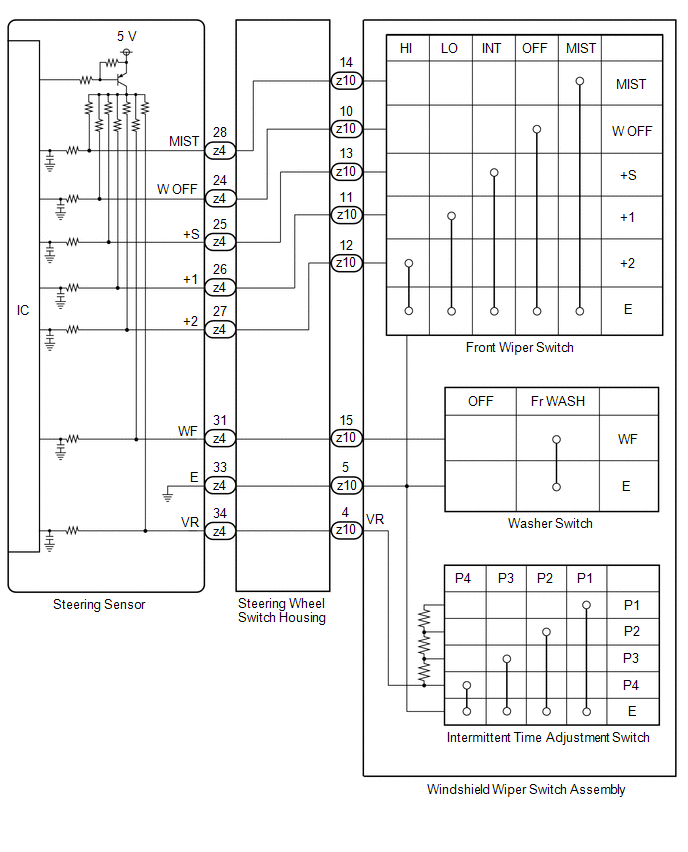
PROCEDURE
| 1. |
READ VALUE USING TECHSTREAM |
(a) Connect the Techstream to the DLC3.
(b) Turn the engine switch on (IG).
(c) Turn the Techstream on.
(d) Enter the following menus: Chassis / Steering Angle Sensor / Data List.
(e) Read the Data List according to the display on the Techstream.
Chassis > Steering Angle Sensor > Data List
|
Tester Display | Measurement Item |
Range | Normal Condition |
Diagnostic Note |
|
Wiper OFF Switch | Front wiper switch OFF position signal |
OFF or ON | OFF: Front wiper switch not in OFF position
ON: Front wiper switch in OFF position |
- |
| Wiper Auto/Int Switch |
Front wiper switch INT position signal |
OFF or ON | OFF: Front wiper switch not in INT position
ON: Front wiper switch in INT position |
- |
| Wiper Lo Switch |
Front wiper switch LO position signal |
OFF or ON | OFF: Front wiper switch not in LO position
ON: Front wiper switch in LO position |
- |
| Wiper Hi Switch |
Front wiper switch HI position signal |
OFF or ON | OFF: Front wiper switch not in HI position
ON: Front wiper switch in HI position |
- |
| Wiper Mist Switch |
Front wiper switch MIST position signal |
OFF or ON | OFF: Front wiper switch not in MIST position
ON: Front wiper switch in MIST position |
- |
| Washer Switch |
Washer switch ON position signal |
OFF or ON | OFF: Front washer switch not in ON position
ON: Front washer switch in ON position |
- |
| Intermittent Time Volume |
Intermittent time adjustment switch condition |
Shortest, Shorter, Longer, Longest |
Shortest: P4 Shorter: P3 Longer: P2 Longest: P1 |
* |
- *: Refer to Inspection for each position of the switch.
Click here 
Chassis > Steering Angle Sensor > Data List
|
Tester Display |
| Wiper OFF Switch |
|
Wiper Auto/Int Switch |
|
Wiper Lo Switch |
|
Wiper Hi Switch |
|
Wiper Mist Switch |
|
Washer Switch |
|
Intermittent Time Volume |
OK:
The Techstream display changes correctly in response to the windshield wiper switch assembly operation.
| OK |
 | PROCEED TO NEXT SUSPECTED AREA SHOWN IN PROBLEM SYMPTOMS TABLE |
|
NG |
 | |
| 2. |
INSPECT WINDSHIELD WIPER SWITCH ASSEMBLY |
(a) Remove the windshield wiper switch assembly.
Click here

(b) Inspect the windshield wiper switch assembly.
Click here 
| NG |
 | REPLACE WINDSHIELD WIPER SWITCH ASSEMBLY |
|
OK |
 | |
| 3. |
INSPECT STEERING WHEEL SWITCH HOUSING |
(a) Remove the steering wheel switch housing.
Click here

(b) Inspect the steering wheel switch housing.
Click here 
| OK |
 | REPLACE STEERING SENSOR |
| NG |
 | REPLACE STEERING WHEEL SWITCH HOUSING |
Wiper Motor Power Source Circuit
DESCRIPTION
This circuit is the power source circuit for the windshield wiper motor assembly.
WIRING DIAGRAM
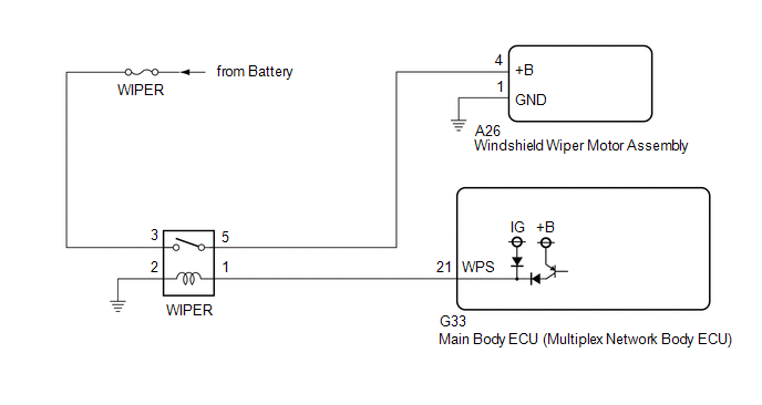
CAUTION / NOTICE / HINT
NOTICE:
- Inspect the fuses of circuits related to this system before performing the following procedure.
- Before replacing the main body ECU (multiplex network body ECU), refer to Registration.
Click here 
PROCEDURE
|
1. | READ VALUE USING TECHSTREAM |
(a) Connect the Techstream to the DLC3.
(b) Turn the engine switch on (IG).
(c) Turn the Techstream on.
(d) Enter the following menus: Body Electrical / Wiper / Data List.
(e) Read the Data List according to the display on the Techstream.
Body Electrical > Wiper > Data List
|
Tester Display | Measurement Item |
Range | Normal Condition |
Diagnostic Note |
|
Motor Power Supply Voltage |
Front wiper motor assembly supply voltage status |
Min.: 0 V Max.: 63 V |
Almost the same as actual front wiper motor assembly voltage |
- |
Body Electrical > Wiper > Data List
|
Tester Display |
| Motor Power Supply Voltage |
OK:
The Techstream display is normal.
| OK |
 | PROCEED TO NEXT SUSPECTED AREA SHOWN IN PROBLEM SYMPTOMS TABLE |
|
NG |
 | |
| 2. |
CHECK HARNESS AND CONNECTOR (WINDSHIELD WIPER MOTOR ASSEMBLY - BODY GROUND) |
(a) Disconnect the A26 windshield wiper motor assembly connector.
(b) Measure the resistance according to the value(s) in the table below.
Standard Resistance:
|
Tester Connection | Condition |
Specified Condition |
|
A26-1 (GND) - Body ground |
Always | Below 1 Ω |
| NG |
 | REPAIR OR REPLACE HARNESS OR CONNECTOR |
|
OK |
 | |
| 3. |
CHECK HARNESS AND CONNECTOR (POWER SOURCE - WINDSHIELD WIPER MOTOR ASSEMBLY) |
(a) Measure the voltage according to the value(s) in the table below.
Standard Voltage:
|
Tester Connection | Condition |
Specified Condition |
|
A26-4 (+B) - Body ground |
Engine switch on (IG) |
11 to 14 V |
|
Less than approximately 60 seconds after engine switch turned off |
|
Approximately 60 seconds or more after engine switch turned off |
Below 1 V |
| OK |
 | REPLACE WINDSHIELD WIPER MOTOR ASSEMBLY |
|
NG |
 | |
(a) Inspect the WIPER relay.
Click here 
| NG |
 | REPLACE WIPER RELAY |
|
OK |
 | |
| 5. |
CHECK HARNESS AND CONNECTOR (POWER SOURCE - WIPER RELAY) |
(a) Measure the voltage according to the value(s) in the table below.
Standard Voltage:
|
Tester Connection | Condition |
Specified Condition |
|
3 (WIPER relay) - Body ground |
Always | 11 to 14 V |
| NG |
 | REPAIR OR REPLACE HARNESS OR CONNECTOR |
|
OK |
 | |
| 6. |
CHECK HARNESS AND CONNECTOR (WIPER RELAY - BODY GROUND) |
(a) Measure the resistance according to the value(s) in the table below.
Standard Resistance:
|
Tester Connection | Condition |
Specified Condition |
|
2 (WIPER relay) - Body ground |
Always | Below 1 Ω |
| NG |
 | REPAIR OR REPLACE HARNESS OR CONNECTOR |
|
OK |
 | |
| 7. |
CHECK HARNESS AND CONNECTOR (WIPER RELAY - WINDSHIELD WIPER MOTOR ASSEMBLY) |
(a) Measure the resistance according to the value(s) in the table below.
Standard Resistance:
|
Tester Connection | Condition |
Specified Condition |
|
5 (WIPER relay) - A26-4 (+B) |
Always | Below 1 Ω |
|
5 (WIPER relay) or A26-4 (+B) - Body ground |
Always | 10 kΩ or higher |
| NG |
 | REPAIR OR REPLACE HARNESS OR CONNECTOR |
|
OK |
 | |
| 8. |
CHECK HARNESS AND CONNECTOR (WIPER RELAY - MAIN BODY ECU (MULTIPLEX NETWORK BODY ECU)) |
(a) Disconnect the G33 main body ECU (multiplex network body ECU) connector.
(b) Measure the resistance according to the value(s) in the table below.
Standard Resistance:
|
Tester Connection | Condition |
Specified Condition |
|
1 (WIPER relay) - G33-21 (WPS) |
Always | Below 1 Ω |
|
1 (WIPER relay) or G33-21 (WPS) - Body ground |
Always | 10 kΩ or higher |
| OK |
 | REPLACE MAIN BODY ECU (MULTIPLEX NETWORK BODY ECU) |
| NG |
 | REPAIR OR REPLACE HARNESS OR CONNECTOR |


