Toyota Avalon (XX50): Wiper And Washer System(for Hv Model)
How To Proceed With Troubleshooting
CAUTION / NOTICE / HINT
HINT:
- Use the following procedure to troubleshoot the wiper and washer system.
PROCEDURE
|
1. | VEHICLE BROUGHT TO WORKSHOP |
|
NEXT |
 | |
| 2. |
CUSTOMER PROBLEM ANALYSIS |
HINT:
- In troubleshooting, confirm that the problem symptoms have been
accurately identified. Preconceptions should be discarded in order to
make an accurate judgment. To clearly understand what the problem
symptoms are, it is extremely important to ask the customer about the
problem and the conditions at the time the malfunction occurred.
- Gather as much information as possible for reference. Past problems that seem unrelated may also help in some cases.
- The following 5 items are important points for problem analysis:
|
What |
Vehicle model, system name |
|
When |
Date, time, occurrence frequency |
|
Where |
Road conditions |
|
Under what conditions? |
Driving conditions, weather conditions |
|
How did it happen? |
Problem symptoms |
|
NEXT |
 | |
| 3. |
READ OUT AND SAVE OPERATION HISTORY |
NOTICE:
- If the vehicle or vehicle controls are operated (for example, during
initial inspection when the vehicle is brought in for repair) before
operation history has been read out and saved, the operation history
information could be lost.
- The function "Read operation history" uses the current system time
setting inside the Techstream and the time counter inside the
controlling ECU to calculate the timings shown in the operation history.
For this reason, before reading out the operation history, first make
sure that the Techstream system clock is accurately set to the current
time.
(a) Read out and save operation history using the Techstream.
Click here

Body Electrical > Wiper > Utility
|
Tester Display |
| Operation History |
|
NEXT |
 | |
(a) Measure the auxiliary battery voltage with power switch off.
Standard Voltage:
11 to 14 V
If the voltage is below 11 V, recharge or replace the auxiliary battery before proceeding to the next step.
(b) Check the fuses and relays.
(c)
Check the connector connections and terminals to make sure that there
are no abnormalities such as loose connections, deformation, etc.
|
NEXT |
 | |
| 5. |
CHECK COMMUNICATION FUNCTION OF CAN COMMUNICATION SYSTEM* |
(a) Using the Techstream, check for CAN communication system DTCs.
Click here

|
Result | Proceed to |
|
CAN DTCs are not output |
A |
| CAN DTCs are output |
B |
| B |
 | GO TO CAN COMMUNICATION SYSTEM |
|
A |
 | |
(a) Check for DTCs.
Body Electrical > Wiper > Trouble Codes Body Electrical > Main Body > Trouble Codes
|
Result | Proceed to |
|
DTCs are not output | A |
|
DTCs are output | B |
| B |
 | GO TO DIAGNOSTIC TROUBLE CODE CHART |
|
A |
 | |
| 7. |
PROBLEM SYMPTOMS TABLE |
(a) Refer to Problem Symptoms Table.
Click here 
|
Result | Proceed to |
|
Fault is not listed in Problem Symptoms Table |
A |
| Fault is listed in Problem Symptoms Table |
B |
| B |
 | GO TO PROBLEM SYMPTOMS TABLE |
|
A |
 | |
| 8. |
OVERALL ANALYSIS AND TROUBLESHOOTING* |
(a) Operation Check.
Click here 
(b) Data List / Active Test
Click here 
(c) Terminals of ECU
Click here 
(d) Fail-safe Chart
Click here 
(e) Inspection
(f) On-vehicle inspection
|
NEXT |
 | |
| 9. |
ADJUST, REPAIR OR REPLACE |
|
NEXT |
 | |
| NEXT |
 | END |
Parts Location
PARTS LOCATION
ILLUSTRATION
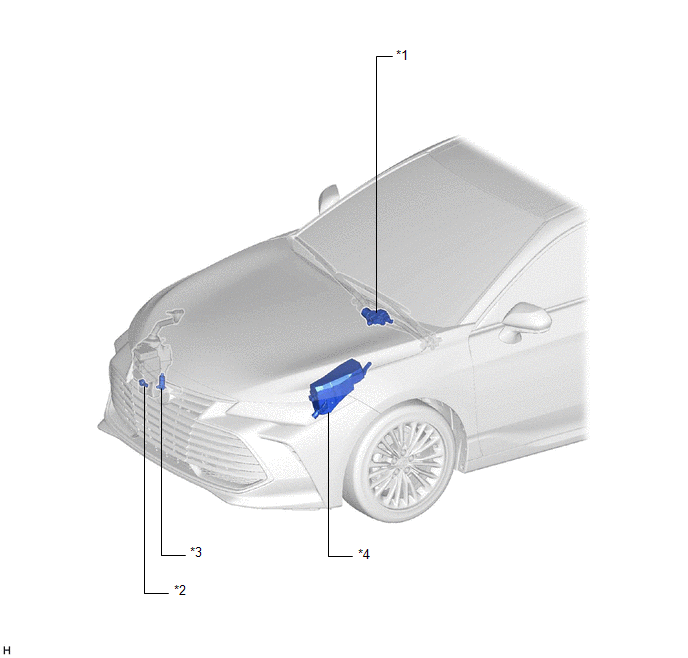
|
*1 | WINDSHIELD WIPER MOTOR ASSEMBLY |
*2 | LEVEL WARNING SWITCH ASSEMBLY |
|
*3 | WINDSHIELD WASHER MOTOR AND PUMP ASSEMBLY |
*4 | NO. 1 ENGINE ROOM RELAY BLOCK AND NO. 1 JUNCTION BLOCK ASSEMBLY
- WIPER FUSE - WIPER RELAY - WASHER RELAY |
ILLUSTRATION
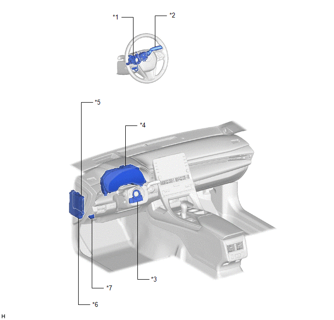
|
*1 | STEERING WHEEL SWITCH HOUSING |
*2 | WINDSHIELD WIPER SWITCH ASSEMBLY |
|
*3 | STEERING SENSOR |
*4 | COMBINATION METER ASSEMBLY |
|
*5 | MAIN BODY ECU (MULTIPLEX NETWORK BODY ECU) |
*6 | INSTRUMENT PANEL JUNCTION BLOCK ASSEMBLY
- WASHER FUSE |
|
*7 | DLC3 |
- | - |
Precaution
PRECAUTION
PRECAUTION FOR DISCONNECTING CABLE FROM NEGATIVE AUXILIARY BATTERY TERMINAL
NOTICE:
When
disconnecting the cable from the negative (-) auxiliary battery
terminal, initialize the following systems after the cable is
reconnected.
|
System Name | See Procedure |
|
Lane Departure Alert System (w/ Steering Control) |
 |
|
Intelligent Clearance Sonar System |
|
Parking Assist Monitor System |
|
Panoramic View Monitor System |
|
Pre-collision System |
|
Lighting System (for HV Model with Cornering Light) |
PRECAUTION FOR WASHER NOZZLE ADJUSTMENT
(a) Do not clean or adjust the washer nozzle with a safety pin, etc. because:
(1) The washer nozzle tip is made of resin and may be damaged.
(2)
Adjustment is not necessary for this spray type washer nozzle. If it is
necessary to change the nozzle angle, replace the washer nozzle with
one that has a different nozzle angle.
Click here

(b)
If the washer nozzle is clogged with wax, etc., remove it and clean the
nozzle hole with a soft resin brush or other cleaning tool.
System Description
SYSTEM DESCRIPTION
FRONT WIPER AND WASHER CONTROL FUNCTION
|
Control/Function | Description |
|
Wiper speed regulation | Maintains the default speed of the wipers even when the supply voltage or resistance changes. |
|
Wiper speed HI to LO transition control |
Smoothly controls the change in speed of the wipers when the wiper speed is changed from HI to LO. |
|
Service position control | Stops
the front wipers at the top of their stroke when the windshield wiper
switch assembly is held in the MIST position for 2 seconds or more
within approximately 45 seconds after the power switch is turned off.
HINT:
- The front wipers can be returned from the service position by turning
the power switch on (IG) and operating the windshield wiper switch
assembly.
- If the MIST function is operated when the front wipers are in the
service position, the front wipers will return to the park position.
- The front wipers must be in the service position when locking them back*.
|
| Engine hood interference damage reduction function |
- Operates the windshield wiper motor assembly at a slow speed for the
first cycle when returning from the service position to minimize damage
to the engine hood if a wiper arm is still in the lock-back position.
- Moves the wipers a short distance in reverse if a wiper arm in the
lock-back position contacts the engine hood and the windshield wiper
motor locks up.
|
| Self-locking control |
Holds the wipers in the park position when the power switch is on (IG). |
|
Protection mode |
- Limits the operation of the windshield wiper motor assembly when
excessive load is detected, in order to protect the wiper and washer
system.
- Refer to Fail-safe chart.
Click here 
|
| MIST function |
Operates the wipers in LO when the windshield wiper switch assembly is held in the MIST position. |
|
Vehicle speed sensing type adjustable intermittent wiper control |
Controls the delay of the front wipers when the windshield wiper switch assembly is in the INT position.
HINT:
- The intermittent operation interval is controlled by the intermittent
time adjustment switch of the windshield wiper switch assembly.
- The intermittent operation interval of delay changes in accordance with the vehicle speed.
- When the windshield wiper switch assembly is in the INT position and the
vehicle is stopped, the wipers operate for 1 cycle when the vehicle
starts off.
- When the intermittent time adjustment switch is moved to a faster
position, the delay is reset and control begins according to the new
setting.
|
| Washer cooperation |
- When the washer switch is operated for 0.5 seconds or more, the front wipers operate in LO.
- When the washer switch is released, the front wipers operate in LO for 3 additional cycles.
NOTICE: If the
washer switch is operated for approximately 40 seconds or more,
operation of the windshield washer motor and pump assembly is stopped to
prevent burnout, and the front wipers are returned to the park
position. |
| Drip prevention wiper function |
Approximately
3 seconds after washer cooperation completes, operates the front wipers
for 1 cycle to remove any remaining washer fluid. HINT: This
function only operates when the vehicle is stationary and will stop
operating at a vehicle speed of approximately 5 km/h (3 mph) or more. |
|
Vehicle stopped wiper control | If
the vehicle is stopped and the windshield wiper switch assembly is
moved to the LO position, the front wipers will operate in LO for 3
cycles and then at a 2.5 second interval. |
- *: Function that allows the front wiper arms to be folded back such as when replacing the wiper rubber.
OTHER FUNCTIONS
|
Control/Function | Description |
|
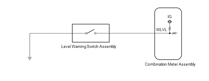
Washer fluid level low warning | Displays
"Windshield Washer Fluid Low" on the multi-information display in the
combination meter assembly when the washer fluid level is low. |
|
Wiper system warning | Displays
"Wiper System Malfunction Visit Your Dealer" on the multi-information
display in the combination meter assembly when the wiper and washer
system is malfunctioning. |
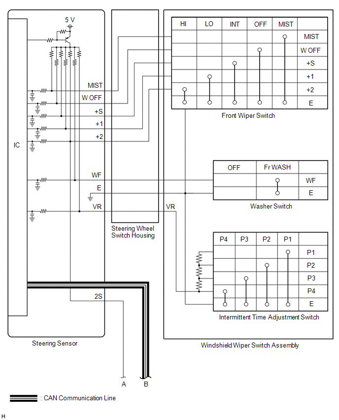
System Diagram
SYSTEM DIAGRAM
FRONT WIPER AND WASHER SYSTEM
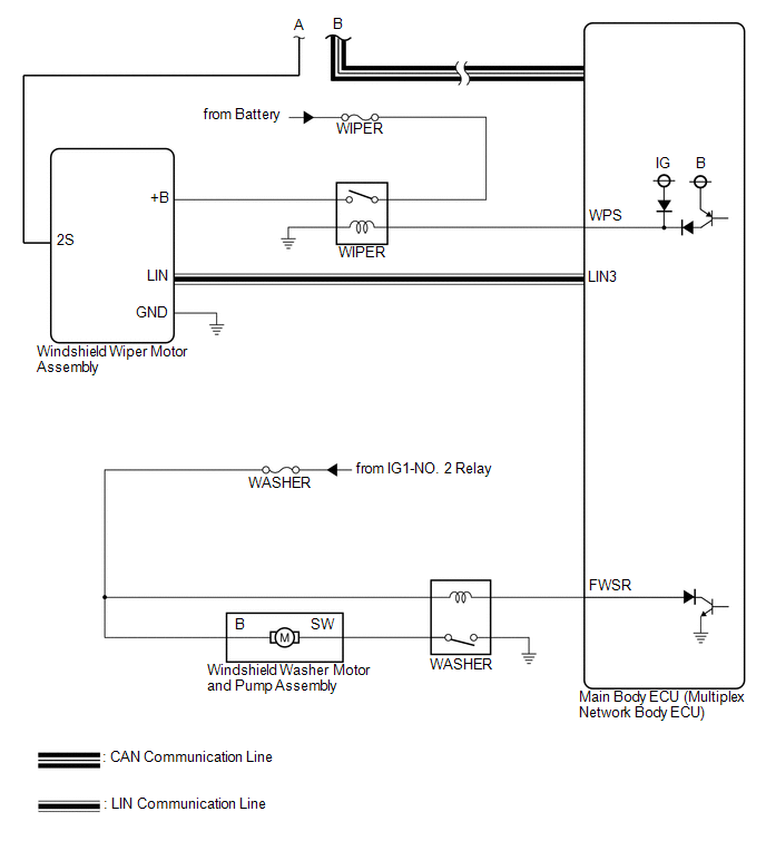
WASHER FLUID LEVEL WARNING SYSTEM
