Components
COMPONENTS
ILLUSTRATION
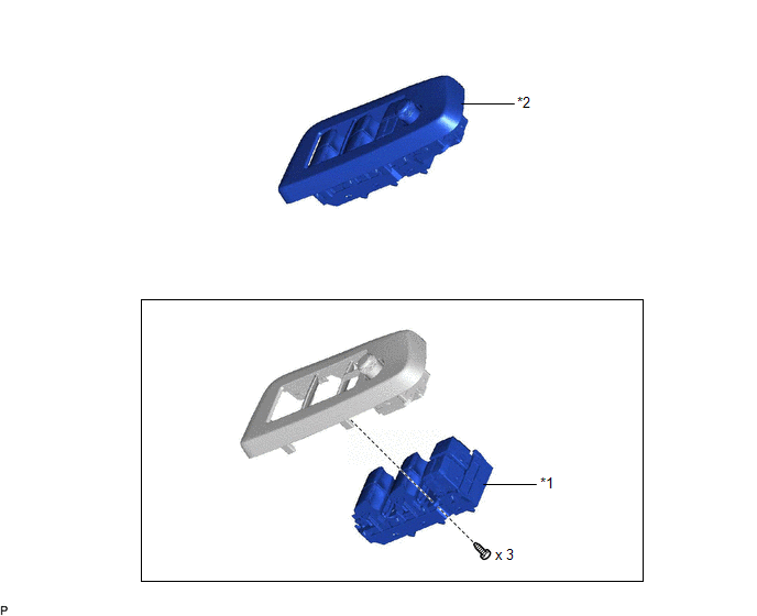
|
*1 | MULTIPLEX NETWORK MASTER SWITCH ASSEMBLY |
*2 | MULTIPLEX NETWORK MASTER SWITCH ASSEMBLY WITH FRONT DOOR UPPER ARMREST BASE PANEL |
Inspection
INSPECTION
PROCEDURE
1. INSPECT MULTIPLEX NETWORK MASTER SWITCH ASSEMBLY
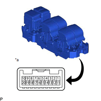
| (a) Check that the LEDs illuminate. (1) Apply auxiliary battery voltage to the multiplex network master switch assembly and check that the LEDs illuminate. OK:
If the result is not as specified, replace the multiplex network master switch assembly. |
|
Installation
INSTALLATION
PROCEDURE
1. INSTALL MULTIPLEX NETWORK MASTER SWITCH ASSEMBLY
(a) Install the multiplex network master switch assembly with the 3 screws.
2. INSTALL MULTIPLEX NETWORK MASTER SWITCH ASSEMBLY WITH FRONT DOOR UPPER ARMREST BASE PANEL
Click here 
Removal
REMOVAL
PROCEDURE
1. REMOVE MULTIPLEX NETWORK MASTER SWITCH ASSEMBLY WITH FRONT DOOR UPPER ARMREST BASE PANEL
Click here 
2. REMOVE MULTIPLEX NETWORK MASTER SWITCH ASSEMBLY
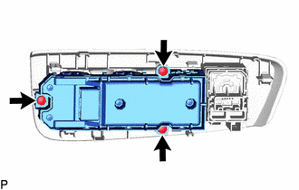
| (a) Remove the 3 screws and multiplex network master switch assembly. |
|
Toyota Avalon (XX50) 2019-2022 Service & Repair Manual > Electronically Controlled Brake System(for Hv Model): Power Supply Drive Circuit (C1257). HV Control System Regenerative Malfunction (C1259,C1310). Abnormal Zero Point of Steering Angle Sensor (C1290)
Power Supply Drive Circuit (C1257) DESCRIPTION The skid control ECU (brake booster with master cylinder assembly) detects a drop in accumulator pressure according to the signals from the accumulator pressure sensor, then operates and stops the motor relay as well as the pump motor. The skid control ...