Installation
INSTALLATION
PROCEDURE
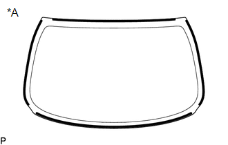
1. INSTALL NO. 1 BACK WINDOW GLASS STOPPER (for 2-piece Type)
| (a) Install 2 new No. 1 back window glass stoppers to the vehicle body as shown in the illustration.
HINT: Only
2-piece type back window glass stoppers are provided as supply parts.
Use 2-piece type stoppers as replacements even if 1-piece type stoppers
were originally installed. | |
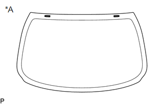
2. INSTALL NO. 2 BACK WINDOW GLASS STOPPER (for 2-piece Type)
(a) Using a brush or sponge, coat the installation area of 2 new No. 2 back window glass stoppers with primer G.
NOTICE:
- Do not apply too much primer G.
- Allow the primer G to dry for 3 minutes or more.
- Throw away any leftover primer G.
HINT:
If an area other than specified is coated by accident, wipe off the primer G with a clean piece of cloth before it dries.
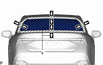
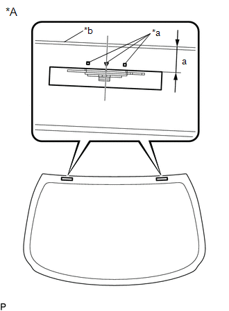
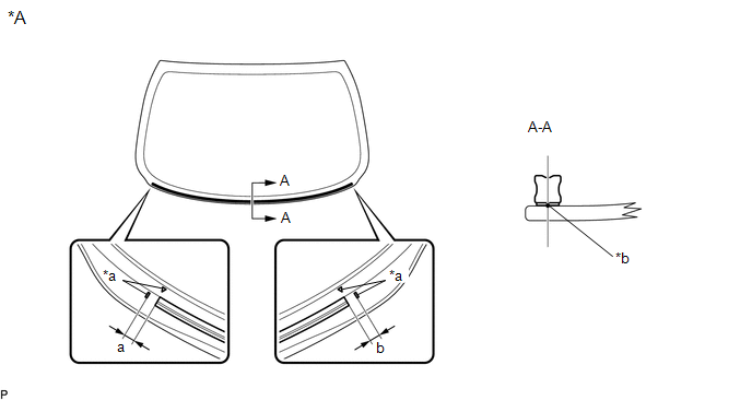
| (b) Install 2 new No. 2 back window glass stoppers to the back window glass as shown in the illustration.
Standard Dimension: |
Area | Dimension | |
a | 17.7 to 18.7 mm (0.697 to 0.736 in.) |
HINT: Only
2-piece type back window glass stoppers are provided as supply parts.
Use 2-piece type stoppers as replacements even if 1-piece type stoppers
were originally installed. |
 |
|
*A | Back Side | |
*a | Ceramic Notch | |
*b | Back Window Glass Edge Side | | |
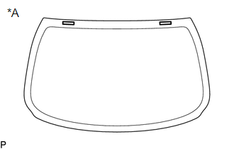
3. INSTALL BACK WINDOW GLASS ADHESIVE DAM
(a) Using a brush or sponge, coat the installation area of a new back window glass adhesive dam with primer G.
NOTICE:
- Do not apply too much primer G.
- Allow the primer G to dry for 3 minutes or more.
- Throw away any leftover primer G.
HINT:
If an area other than specified is coated by accident, wipe off the primer G with a clean piece of cloth before it dries.
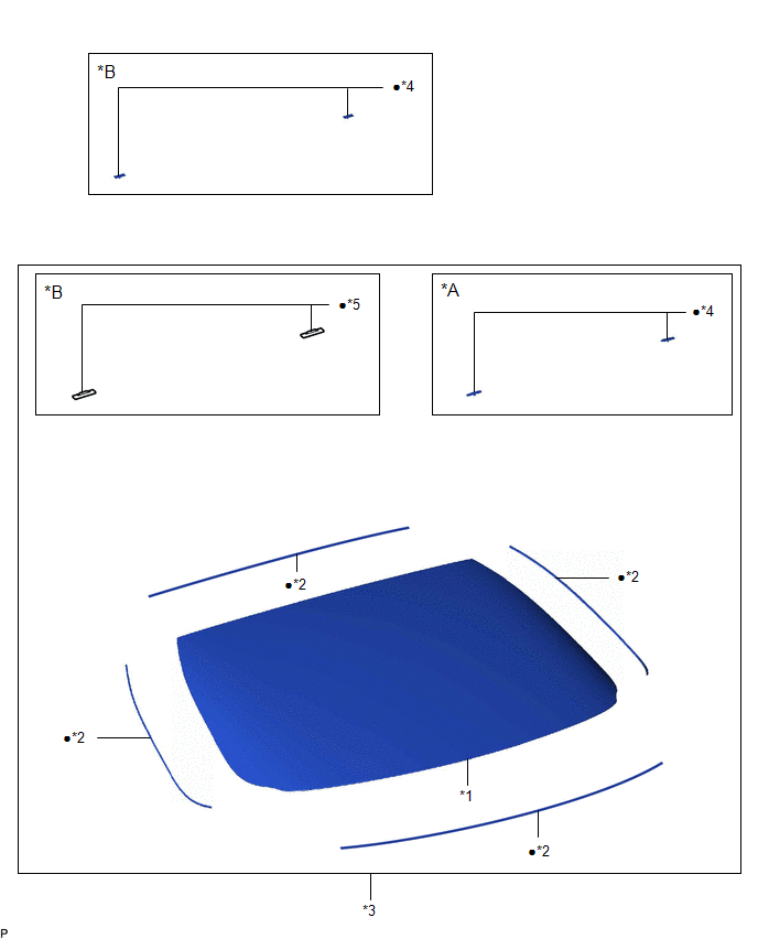
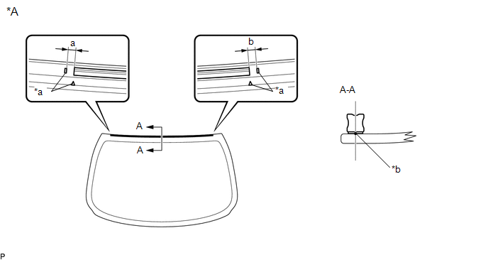
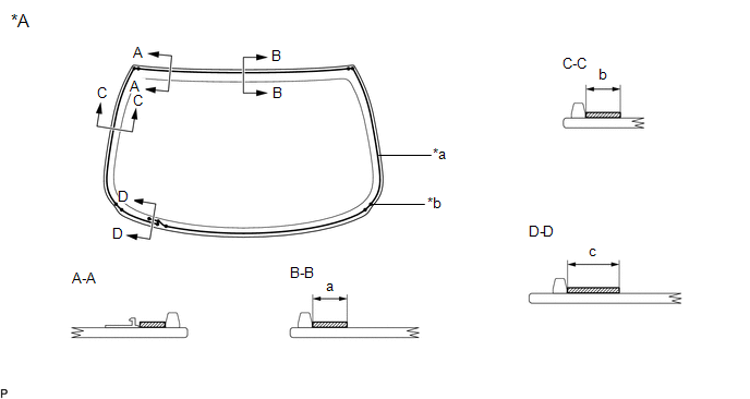
(b) Install a new back window glass adhesive dam to the back window glass as shown in the illustration.
|
*A | Back Side |
- | - |
|
*a | Ceramic Notch |
*b | Back Window Glass Adhesive Dam Positioning Center |
Standard Dimension:
|
Area | Dimension |
|
a | 0 to 10.0 mm (0 to 0.394 in.) |
|
b | 0 to 10.0 mm (0 to 0.394 in.) |
(c) Using a brush or sponge, coat the installation area of 2 new back window glass adhesive dams with primer G.
NOTICE:
- Do not apply too much primer G.
- Allow the primer G to dry for 3 minutes or more.
- Throw away any leftover primer G.
HINT:
If an area other than specified is coated by accident, wipe off the primer G with a clean piece of cloth before it dries.
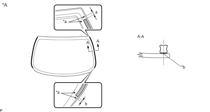
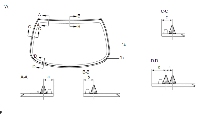
(d) Install 2 new back window glass adhesive dams to the back window glass as shown in the illustration.
|
*A | Back Side |
- | - |
|
*a | Ceramic Notch |
*b | Back Window Glass Adhesive Dam Positioning Center |
Standard Dimension:
|
Area | Dimension |
|
a | 0 to 10.0 mm (0 to 0.394 in.) |
|
b | 0 to 10.0 mm (0 to 0.394 in.) |
(e) Using a brush or sponge, coat the installation area of a new back window glass adhesive dam with primer G.
NOTICE:
- Do not apply too much primer G.
- Allow the primer G to dry for 3 minutes or more.
- Throw away any leftover primer G.
HINT:
If an area other than specified is coated by accident, wipe off the primer G with a clean piece of cloth before it dries.
(f) Install a new back window glass adhesive dam to the back window glass as shown in the illustration.
|
*A | Back Side |
- | - |
|
*a | Ceramic Notch |
*b | Back Window Glass Adhesive Dam Positioning Center |
Standard Dimension:
|
Area | Dimension |
|
a | 0 to 10.0 mm (0 to 0.394 in.) |
|
b | 0 to 10.0 mm (0 to 0.394 in.) |
4. INSTALL BACK WINDOW GLASS SUB-ASSEMBLY
| (a) Position the back window glass sub-assembly. (1) Using suction cups, place the back window glass sub-assembly in the correct position.
(2) Check that the whole contact surface of the back window glass sub-assembly rim is perfectly even.
(3) Align the matchmarks on the back window glass sub-assembly and vehicle body.
NOTICE: Check that the back window glass stoppers are engaged to the vehicle body correctly.
(4) Remove the back window glass sub-assembly. | |
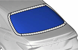
(b) Using a brush, coat the installation surface on the vehicle body with primer M.
NOTICE:
- Do not coat the adhesive with primer M.
- Do not apply too much primer M.
- Allow the primer M to dry for 3 minutes or more.
- Throw away any leftover primer M.
HINT:
If an area other than specified is coated by accident, wipe off the primer M with a clean piece of cloth before it dries.
(c) Using a brush or sponge, coat the adhesive application area with primer G.
|
*A | Back Side |
- | - |
|
*a | Adhesive center position |
*b | Ceramic Notch |
 |
Primer G | - |
- |
Standard Dimension:
|
Area | Dimension |
|
a | 12.5 mm (0.492 in.) or more |
|
b | 12.4 mm (0.488 in.) or more |
|
c | 19.0 mm (0.748 in.) or more |
NOTICE:
- Do not apply too much primer G.
- Allow the primer G to dry for 3 minutes or more.
- Throw away any leftover primer G.
HINT:
- Apply primer G to the ceramic notches.
- If an area other than specified is coated by accident, wipe off the primer G with a clean piece of cloth before it dries.
(d) Apply adhesive to the back window glass sub-assembly.
Adhesive:
Toyota Genuine Windshield Glass Adhesive (High modulus Type) or Equivalent
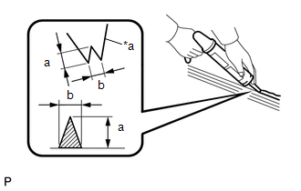
| (1) Cut off the tip of the cartridge nozzle as shown in the illustration.
Standard Dimension: |
Area | Dimension | |
a | 12.0 to 15.0 mm (0.472 to 0.591 in.) | |
b | 8.0 to 11.0 mm (0.315 to 0.433 in.) | |
|
(2) Load the sealer gun with the cartridge.
(3) Apply adhesive to the back window glass sub-assembly as shown in the illustration.
|
*A | Back Side |
- | - |
|
*a | Adhesive Positioning Center |
*b | Ceramic Notch |
|
|
Adhesive | - |
- |
Standard Dimension:
|
Area | Dimension |
|
a | 12.0 to 15.0 mm (0.472 to 0.591 in.) |
|
b | 13.5 mm (0.531 in.) |
|
c | 13.4 mm (0.528 in.) |
|
d | 17.5 mm (0.689 in.) |
|
e | 8.0 to 11.0 mm (0.315 to 0.433 in.) |
HINT:
Apply adhesive to the ceramic notches.
(e) Install the back window glass sub-assembly.
| (1)
Using suction cups, position the back window glass sub-assembly so that
the matchmarks are aligned, and press it in gently along the rim.
NOTICE:
- Check that the back window glass stoppers are engaged to the vehicle body correctly.
- Check the clearance between the vehicle body and back window glass sub-assembly.
| |
(2)
Lightly press the outer surface of the back window glass sub-assembly
to ensure that the back window glass is securely fit to the vehicle
body.
HINT:
Press the glass with a force of 98 N (10 kgf, 22.0 lbf) or more.
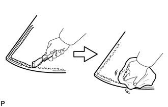
(3) Using a scraper, remove any excess or protruding adhesive.
(4) Hold the back window glass sub-assembly using protective tape until the applied adhesive becomes hard.
HINT:
Follow
the instructions supplied by the adhesive manufacturer or in the
corresponding instruction manual for the minimum amount of time
necessary to wait before driving the vehicle.
(f) Connect each connector.
5. INSPECT FOR LEAK
(a) After the adhesive has hardened, apply water from the outside of the vehicle. Check that no water leaks into the cabin.
(b) If water leaks into the cabin, allow the water to dry and add adhesive.
(c) Remove the protective tape.
6. INSTALL PACKAGE TRAY TRIM PANEL ASSEMBLY
Click here 
7. INSTALL REAR SEAT SHOULDER BELT COVER
Click here
8. INSTALL CENTER STOP LIGHT SET
Click here
9. CONNECT REAR SEAT 3 POINT TYPE BELT ASSEMBLY LH
Click here
10. CONNECT REAR SEAT 3 POINT TYPE BELT ASSEMBLY RH
HINT:
Use the same procedure as for the LH side.
11. INSTALL ROOF HEADLINING ASSEMBLY
Click here
Removal
REMOVAL
CAUTION / NOTICE / HINT
The
necessary procedures (adjustment, calibration, initialization, or
registration) that must be performed after parts are removed and
installed, or replaced during back window glass sub-assembly
removal/installation are shown below.
Necessary Procedure After Parts Removed/Installed/Replaced (for Gasoline Model) |
Replaced Part or Performed Procedure |
Necessary Procedure | Effect/Inoperative Function When Necessary Procedures are not Performed |
Link |
|
*: When performing learning using the Techstream.
Click here  |
|
Disconnect cable from negative battery terminal |
Perform steering sensor zero point calibration |
Lane departure alert system (w/ Steering Control) |
|
|
Pre-collision system |
|
Intelligent clearance sonar system* |
|
Lighting system (for Gasoline Model with Cornering Light) |
|
Memorize steering angle neutral point |
Parking assist monitor system |
|
|
Panoramic view monitor system |
|
|
Front passenger seat | Zero point calibration (Occupant classification system) |
- Occupant classification system
- Passenger airbag ON/OFF indicator
- Airbag system (Front passenger side)
- Seat belt warning system (Front passenger)
|
|
Necessary Procedure After Parts Removed/Installed/Replaced (for HV Model) |
Replaced Part or Performed Procedure |
Necessary Procedure | Effect/Inoperative Function When Necessary Procedures are not Performed |
Link |
|
*: When performing learning using the Techstream.
Click here |
|
Disconnect cable from negative auxiliary battery terminal |
Perform steering sensor zero point calibration |
Lane departure alert system (w/ Steering Control) |
|
|
Pre-collision system |
|
Intelligent clearance sonar system* |
|
Lighting system (for HV Model with Cornering Light) |
|
Memorize steering angle neutral point |
Parking assist monitor system |
|
|
Panoramic view monitor system |
|
|
Front passenger seat | Zero point calibration (Occupant classification system) |
- Occupant classification system
- Passenger airbag ON/OFF indicator
- Airbag system (Front passenger side)
- Seat belt warning system (Front passenger)
|
|
PROCEDURE
1. REMOVE ROOF HEADLINING ASSEMBLY
Click here
2. DISCONNECT REAR SEAT 3 POINT TYPE BELT ASSEMBLY LH
Click here
3. DISCONNECT REAR SEAT 3 POINT TYPE BELT ASSEMBLY RH
HINT:
Use the same procedure as for the LH side.
4. REMOVE CENTER STOP LIGHT SET
Click here
5. REMOVE REAR SEAT SHOULDER BELT COVER
Click here
6. REMOVE PACKAGE TRAY TRIM PANEL ASSEMBLY
Click here
7. REMOVE BACK WINDOW GLASS SUB-ASSEMBLY
(a) Disconnect each connector.
(b)
Apply protective tape to the area around the installation position of
the back window glass sub-assembly on the vehicle body to prevent it
from being scratched.
 | Protective Tape |
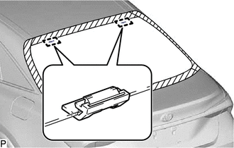
| (c) Place matchmarks on the back window glass sub-assembly and vehicle body at the locations indicated in the illustration.
HINT: Matchmarks are not necessary if the back window glass sub-assembly is not going to be reused. |
|
| (d) Pass a piano wire between the vehicle body and back window glass sub-assembly from the interior. |
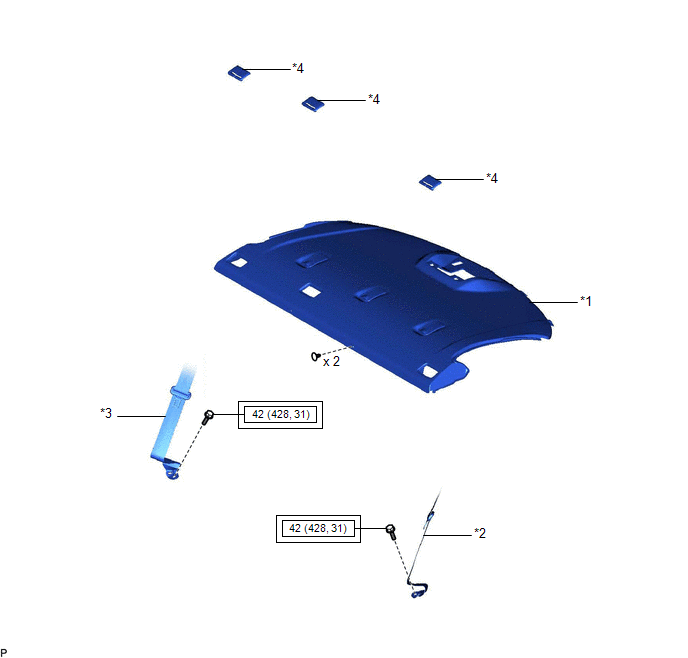
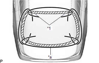 |
|
*1 | Back Window Glass Stopper | |
*a | Piano Wire | | |
(e) Tie both wire ends to wooden blocks or similar objects that can serve as handles.
(f) Cut off the adhesive by pulling the piano wire around the back window glass sub-assembly.
NOTICE:
- When separating the back window glass sub-assembly, be careful not to damage the paint or interior and exterior ornaments.
- When cutting off the adhesive, take care not to damage the connectors on the back window glass sub-assembly.
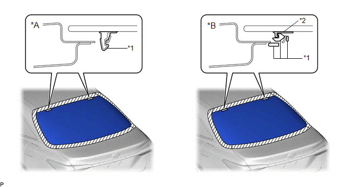
(g) Disengage the back window glass stoppers.
|
*A | for 1-piece Type |
*B | for 2-piece Type |
|
*1 | No. 1 Back Window Glass Stopper |
*2 | No. 2 Back Window Glass Stopper |
NOTICE:
- The No. 1 back window glass stoppers and No. 2 back window glass
stoppers are installed to the back window glass sub-assembly as shown in
the illustration. Be careful not to damage the back window glass
sub-assembly when cutting the adhesive.
- To prevent the back window glass sub-assembly from falling when
performing this operation, be sure to hold the back window glass
sub-assembly using suction cups.
HINT:
Depending on the vehicle, either 1-piece type or 2-piece type stoppers may be present.
(h) Using suction cups, remove the back window glass sub-assembly.
NOTICE:
- Be careful not to drop the back window glass sub-assembly.
- Leave as much adhesive on the vehicle body as possible when removing the back window glass sub-assembly.
8. REMOVE BACK WINDOW GLASS ADHESIVE DAM
(a) When reusing the back window glass:
| (1) Using a scraper, remove the 4 back window glass adhesive dams.
NOTICE:
- Be careful not to damage the back window glass.
- Be sure to replace the back window glass adhesive dams with new ones.
| |
9. REMOVE NO. 1 BACK WINDOW GLASS STOPPER (for 1-piece Type)
(a) When reusing the back window glass:
| (1) Using a scraper, remove the 2 No. 1 back window glass stoppers.
NOTICE:
- Be careful not to damage the back window glass.
- Be sure to replace the 1-piece type No. 1 back window glass stoppers
with new 2-piece type No. 1 and No. 2 back window glass stoppers.
| |
10. REMOVE NO. 2 BACK WINDOW GLASS STOPPER (for 2-piece Type)
(a) When reusing the back window glass:
| (1) Using a scraper, remove the 2 No. 2 back window glass stoppers.
NOTICE:
- Be careful not to damage the back window glass.
- Be sure to replace the No. 2 back window glass stoppers with new ones.
| |
11. REMOVE NO. 1 BACK WINDOW GLASS STOPPER (for 2-piece Type)
| (a) Remove the 2 No. 1 back window glass stoppers. NOTICE:
Be sure to replace the No. 1 back window glass stoppers with new ones. |
|
12. CLEAN BACK WINDOW GLASS
(a) When reusing the back window glass:
| (1) Using a scraper, remove any remaining adhesive dam and adhesive residue from the back window glass.
NOTICE: Be careful not to damage the back window glass. |
|
(2) Clean the outer circumference of the back window glass with a non-residue solvent.
NOTICE:
- Do not touch the back window glass surface after cleaning it.
- Even if using a new back window glass, clean it with a non-residue solvent.
13. CLEAN VEHICLE BODY
(a) Clean and shape the contact surface of the vehicle body.
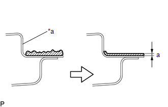
(1) Using a knife, cut away excess adhesive on the contact surface of the vehicle body as shown in the illustration.
|
*a | Vehicle Body |
|
|
Adhesive |
Standard Dimension:
|
Area | Dimension |
|
a | 1.0 mm (0.0394 in.) or more |
NOTICE:
Be careful not to damage the vehicle body.
HINT:
Leave approximately 1.0 mm (0.0394 in.) of adhesive on the vehicle body.
(2) Clean the contact surface of the vehicle body with a piece of cloth saturated with non-residue solvent.
HINT:
Even if all of the adhesive has been removed, clean the vehicle body.