Components
COMPONENTS
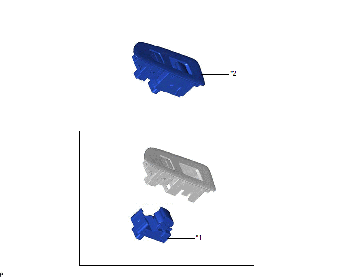
ILLUSTRATION
|
*1 | POWER WINDOW REGULATOR SWITCH ASSEMBLY |
*2 | POWER WINDOW REGULATOR SWITCH ASSEMBLY WITH FRONT DOOR UPPER ARMREST BASE PANEL |
Inspection
INSPECTION
PROCEDURE
1. INSPECT POWER WINDOW REGULATOR SWITCH ASSEMBLY
| (a) Check the switch function. (1) Measure the resistance according to the value(s) in the table below. Standard Resistance:
If the result is not as specified, replace the power window regulator switch assembly. |
|
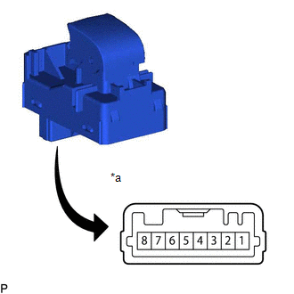
(b) Check that the LED illuminates.
(1) Apply auxiliary battery voltage to the power window regulator switch assembly and check that the LED illuminates.
OK:
|
Battery Connection | Specified Condition |
|---|---|
|
Auxiliary battery positive (+) → 3 Auxiliary battery negative (-) → 1 |
LED illuminates |
If the result is not as specified, replace the power window regulator switch assembly.
Installation
INSTALLATION
PROCEDURE
1. INSTALL POWER WINDOW REGULATOR SWITCH ASSEMBLY
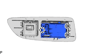
(a) Engage the 3 claws to install the power window regulator switch assembly.
2. INSTALL POWER WINDOW REGULATOR SWITCH ASSEMBLY WITH FRONT DOOR UPPER ARMREST BASE PANEL
Click here 
Removal
REMOVAL
PROCEDURE
1. REMOVE POWER WINDOW REGULATOR SWITCH ASSEMBLY WITH FRONT DOOR UPPER ARMREST BASE PANEL
Click here 
2. REMOVE POWER WINDOW REGULATOR SWITCH ASSEMBLY
| (a) Disengage the 3 claws to remove the power window regulator switch assembly. |
|
Toyota Avalon (XX50) 2019-2022 Service & Repair Manual > Hybrid Control System: Hybrid/EV Battery Precharge Contactor Circuit Short to Ground (P0AE411). Hybrid/EV Battery Precharge Contactor Circuit Short to Auxiliary Battery or Open (P0AE415). Hybrid/EV Battery Sensor Module (P0
Hybrid/EV Battery Precharge Contactor Circuit Short to Ground (P0AE411) DESCRIPTION The SMRs (System Main Relays) are the relays that connect or disconnect the high-voltage system in accordance with commands from the hybrid vehicle control ECU. There are 3 SMRs and 1 system main resistor. SMRB, SMRP ...