Components
COMPONENTS
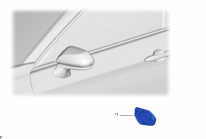
ILLUSTRATION
|
*1 | OUTER MIRROR |
- | - |
Inspection
INSPECTION
PROCEDURE
1. INSPECT OUTER MIRROR RH
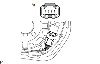
| (a) Check the outer mirror heater operation. (1) Measure the resistance according to the value(s) in the table below. Standard Resistance:
If the result is not as specified, replace the outer mirror RH. |
|
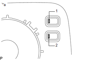
(b) Check the operation of the outer rear view mirror indicator.
NOTICE:
Do not apply a voltage of more than 4.5 V.
(1) Connect 3 new 1.5 V dry-cell batteries in series.
| (2) Apply 4.5 V battery voltage to the terminals of the connector, and check that the outer rear view mirror indicator comes on. OK:
If the result is not as specified, replace the outer mirror RH. |
|
2. INSPECT OUTER MIRROR LH
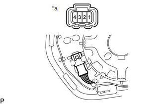
| (a) Check the outer mirror heater operation. (1) Measure the resistance according the value(s) in the table below. Standard Resistance:
If the result is not as specified, replace the outer mirror LH. |
|
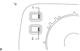
(b) Check the operation of the outer rear view mirror indicator.
NOTICE:
Do not apply a voltage of more than 4.5 V.
(1) Connect 3 new 1.5 V dry-cell batteries in series.
| (2) Apply 4.5 V battery voltage to the terminals of the connector, and check that the outer rear view mirror indicator comes on. OK:
If the result is not as specified, replace the outer mirror LH. |
|
Installation
INSTALLATION
CAUTION / NOTICE / HINT
HINT:
PROCEDURE
1. INSTALL OUTER MIRROR
(a) Connect each connector.
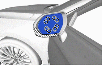
| (b) Engage the 8 claws to install the outer mirror. NOTICE: Do not push the outer mirror with excessive force. Doing so may break the mirror surface. |
|
Removal
REMOVAL
CAUTION / NOTICE / HINT
HINT:
PROCEDURE
1. REMOVE OUTER MIRROR
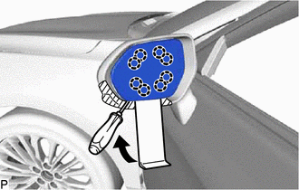
(a) Apply protective tape to the areas shown in the illustration.
 |
Protective Tape |
(b) Push the upper part of the mirror surface and tilt it.
NOTICE:
Do not push the outer mirror with excessive force. Doing so may cause the actuator to come off or break the mirror surface.
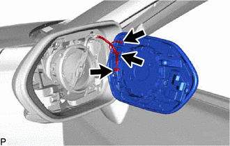
(c) Using a moulding remover and screwdriver, disengage the 8 claws as shown in the illustration.
| (d) Disconnect each connector to remove the outer mirror. |
|
Toyota Avalon (XX50) 2019-2022 Service & Repair Manual > Sfi System: Crankshaft Position - Camshaft Position Correlation Bank 1 Sensor B (P001700,P001900)
DESCRIPTION In the VVT (Variable Valve Timing) system, the appropriate exhaust valve open and close timing is controlled by the ECM. The ECM performs exhaust valve control by performing the following: 1) controlling the exhaust camshaft cam timing oil control solenoid assembly, camshaft timing gear ...