Installation
INSTALLATION
PROCEDURE
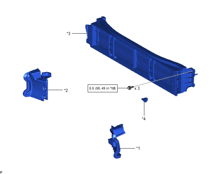
1. INSTALL RADIATOR SHUTTER SUB-ASSEMBLY
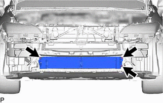
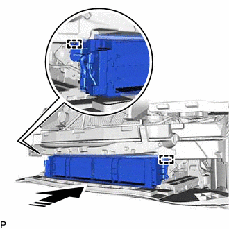
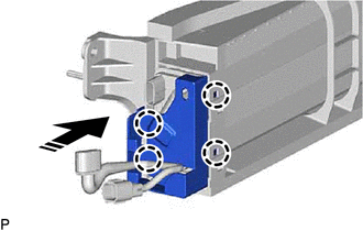
(a) Engage the 2 guides as shown in the illustration.
 |
Install in this Direction |
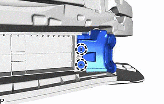
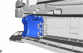
(b) Install the radiator shutter sub-assembly with the 3 bolts.
Torque:
5.5 N·m {56 kgf·cm, 49 in·lbf}
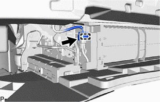
(c) Engage the clamp.
(d) Connect the connector.
2. INSTALL THERMISTOR ASSEMBLY
Click here

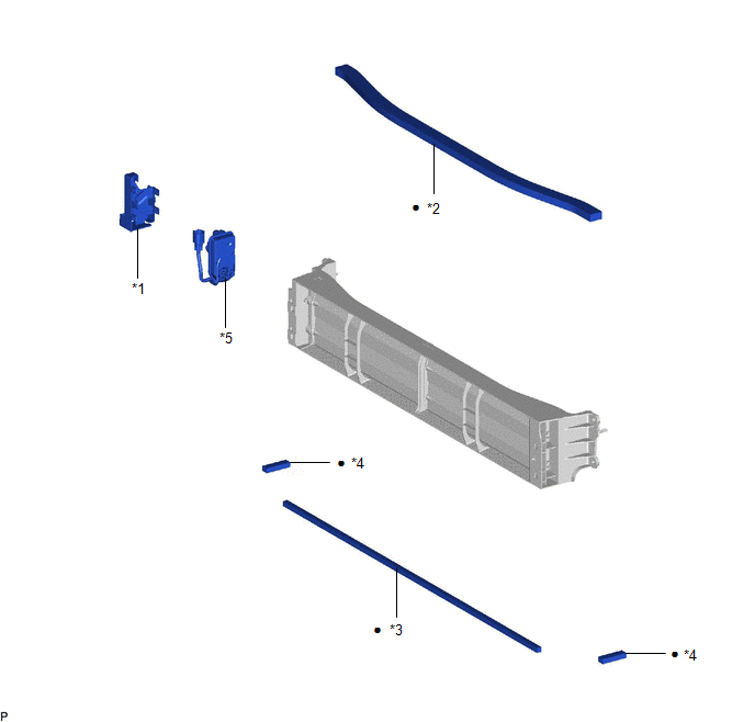
3. INSTALL FRONT RADIATOR SIDE AIR GUIDE PLATE LH
(a) Engage the 2 claws to install the front radiator side air guide plate LH.
4. INSTALL FRONT RADIATOR SIDE AIR GUIDE PLATE RH
(a) Engage the 2 claws to install the front radiator side air guide plate RH.
5. INSTALL FRONT BUMPER ASSEMBLY
Click here
Reassembly
REASSEMBLY
PROCEDURE
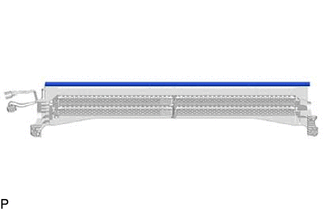
1. INSTALL NO. 2 RADIATOR GRILLE SEAL
HINT:
When installing the No. 2 radiator grille seal, heat the radiator shutter using a heat light.
Heating Temperature |
Item | Temperature |
|
Radiator Shutter | 20 to 30°C (68 to 86°F) |
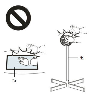
CAUTION:
- Do not touch the heat light and heated parts, touching the heat light may result in burns.
- Touching heated parts for a long time may result in burns.
|
*a | Heated Part |
|
*b | Heat Light |
NOTICE:
Do not heat the radiator shutter excessively.
(a) Clean the radiator shutter surface.
(1) Using a heat light, heat the radiator shutter surface.
(2) Remove any remaining double-sided tape from the radiator shutter.
(3) Wipe off any tape adhesive residue with cleaner.
(b) Remove the release paper from a new No. 2 radiator grille seal.
HINT:
After removing the release paper, keep the exposed adhesive free from foreign matter.
| (c) Install the No. 2 radiator grille seal.
NOTICE:
- If the No. 2 radiator grille seal has been removed, it must be replaced
with a new one as it may be deformed or the strength of its adhesive may
be deteriorated.
- Press the No. 2 radiator grille seal firmly to install it.
| |
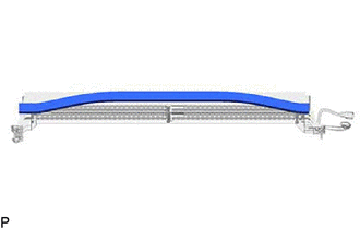
2. INSTALL NO. 1 RADIATOR GRILLE SEAL
HINT:
When installing the No. 1 radiator grille seal, heat the radiator shutter using a heat light.
Heating Temperature |
Item | Temperature |
|
Radiator Shutter | 20 to 30°C (68 to 86°F) |
CAUTION:
- Do not touch the heat light and heated parts, touching the heat light may result in burns.
- Touching heated parts for a long time may result in burns.
|
*a | Heated Part |
|
*b | Heat Light |
NOTICE:
Do not heat the radiator shutter excessively.
(a) Clean the radiator shutter surface.
(1) Using a heat light, heat the radiator shutter surface.
(2) Remove any remaining double-sided tape from the radiator shutter.
(3) Wipe off any tape adhesive residue with cleaner.
(b) Remove the release paper from a new No. 1 radiator grille seal.
HINT:
After removing the release paper, keep the exposed adhesive free from foreign matter.
| (c) Install the No. 1 radiator grille seal.
NOTICE:
- If the No. 1 radiator grille seal has been removed, it must be replaced
with a new one as it may be deformed or the strength of its adhesive may
be deteriorated.
- Press the No. 1 radiator grille seal firmly to install it.
| |
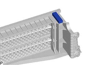
3. INSTALL NO. 3 RADIATOR GRILLE SEAL
HINT:
- When installing the No. 3 radiator grille seal, heat the radiator shutter using a heat light.
- Use the same procedure for the RH side and LH side.
Heating Temperature |
Item | Temperature |
|
Radiator Shutter | 20 to 30°C (68 to 86°F) |
CAUTION:
- Do not touch the heat light and heated parts, touching the heat light may result in burns.
- Touching heated parts for a long time may result in burns.
|
*a | Heated Part |
|
*b | Heat Light |
NOTICE:
Do not heat the radiator shutter excessively.
(a) Clean the radiator shutter surface.
(1) Using a heat light, heat the radiator shutter surface.
(2) Remove any remaining double-sided tape from the radiator shutter.
(3) Wipe off any tape adhesive residue with cleaner.
(b) Remove the release paper from a new No. 3 radiator grille seal.
HINT:
After removing the release paper, keep the exposed adhesive free from foreign matter.
| (c) Install the No. 3 radiator grille seal.
NOTICE:
- If the No. 3 radiator grille seal has been removed, it must be replaced
with a new one as it may be deformed or the strength of its adhesive may
be deteriorated.
- Press the No. 3 radiator grille seal firmly to install it.
| |
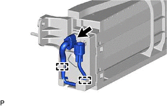
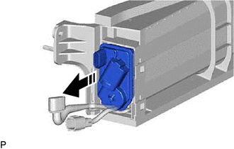
4. INSTALL SWING GRILLE ACTUATOR ASSEMBLY
(a) When installing a new swing grille actuator assembly:
(1) Open the grille shutter fin as shown in the illustration.
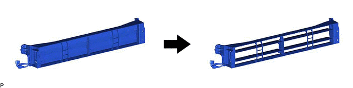
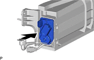
(b) Install the swing grille actuator assembly as shown in the illustration.
 |
Install in this Direction |
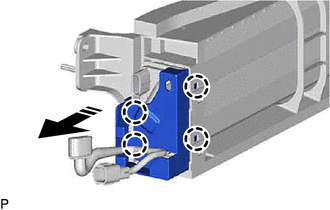
5. INSTALL MOTOR COVER
(a) Engage the 4 claws to install the motor cover as shown in the illustration.
|
|
Install in this Direction |
(c) Connect the connector.
Removal
REMOVAL
CAUTION / NOTICE / HINT
The
necessary procedures (adjustment, calibration, initialization, or
registration) that must be performed after parts are removed and
installed, or replaced during grille shutter removal/installation are
shown below.
Necessary Procedure After Parts Removed/Installed/Replaced |
Replaced Part or Performed Procedure |
Necessary Procedure | Effect/Inoperative Function when Necessary Procedure not Performed |
Link |
|
*: Applies only for when removing and installing or replacing the television camera assembly.
|
| Front television camera assembly, front bumper assembly or radiator grille |
- Television camera view adjustment
- Television camera assembly optical axis adjustment (Back camera position setting)*
| Panoramic View Monitor System |
 for Initialization for Initialization
for Calibration |
|
Front bumper assembly |
- Measurement of ultrasonic sensor detection angle
- Ultrasonic sensor detection angle registration
|
- Intelligent Clearance Sonar System
- Intuitive Parking Assist System
|
|
- Swing grill actuator assembly
- Radiator shutter sub-assembly
| Change grille shutter control mode and/or perform initialization |
Grille Shutter System |
|
PROCEDURE
1. REMOVE FRONT BUMPER ASSEMBLY
Click here
2. REMOVE FRONT RADIATOR SIDE AIR GUIDE PLATE LH
| (a) Disengage the 2 claws to remove the front radiator side air guide plate LH. |
|
3. REMOVE FRONT RADIATOR SIDE AIR GUIDE PLATE RH
| (a) Disengage the 2 claws to remove the front radiator side air guide plate RH. |
|
4. REMOVE THERMISTOR ASSEMBLY
Click here
5. REMOVE RADIATOR SHUTTER SUB-ASSEMBLY
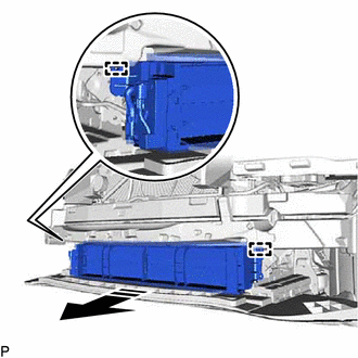
| (a) Disconnect the connector. | |
(b) Disengage the clamp.
(d) Disengage the 2 guides to remove the radiator shutter sub-assembly as shown in the illustration.
 |
Remove in this Direction |