Shutter Control State Maintenance Mode (B1333)
DESCRIPTION
This DTC is stored when the grille shutter system is changed to maintenance mode.
|
DTC No. | Detection Item |
DTC Detection Condition | Trouble Area |
|
B1333 | Shutter Control State Maintenance Mode |
The grille shutter system is changed to maintenance mode. |
Swing grille actuator assembly |
CAUTION / NOTICE / HINT
NOTICE:
If
the swing grille actuator assembly has been replaced with a new one,
perform initialization and change the grille shutter control mode.
Click here

PROCEDURE
(a) Clear the DTCs.
Body Electrical > Grill Shutter > Clear DTCs
|
NEXT |
 | |
(a) Check for DTCs.
Body Electrical > Grill Shutter > Trouble Codes
OK:
DTC B1333 is not output.
| NG |
 | USE SIMULATION METHOD TO CHECK |
|
OK |
 | |
| 3. |
CHANGE GRILLE SHUTTER CONTROL MODE |
(a) Change the grille shutter control mode to normal mode.
Click here 
|
NEXT |
 | |
(a) Check for DTCs.
Body Electrical > Grill Shutter > Trouble Codes
OK:
DTC B1333 is not output.
| OK |
 | END (GRILLE SHUTTER CONTROL MODE WAS NOT CHANGED) |
| NG |
 | REPLACE SWING GRILLE ACTUATOR ASSEMBLY |
Data List / Active Test
DATA LIST / ACTIVE TEST
NOTICE:
In
the table below, the values listed under "Normal Condition" are
reference values. Do not depend solely on these reference values when
deciding whether a part is faulty or not.
HINT:
Using
the Techstream to read the Data List allows the values or states of
switches, sensors, actuators and other items to be read without removing
any parts. This non-intrusive inspection can be very useful because
intermittent conditions or signals may be discovered before parts or
wiring is disturbed. Reading the Data List information early in
troubleshooting is one way to save diagnostic time.
DATA LIST
(a) Connect the Techstream to the DLC3.
(b) Turn the power switch on (IG).
(c) Turn the Techstream on.
(d) Enter the following menus: Body Electrical / Grille Shutter / Data List.
(e) Read the Data List according to the display on the Techstream.
Body Electrical > Grill Shutter > Data List
|
Tester Display | Measurement Item |
Range | Normal Condition |
Diagnostic Note |
|
Shutter Operation State |
Grille shutter operation state |
Standby, Open, Close or Prohibit |
Standby: Grille shutter in standby mode Open: Grille shutter opening
Close: Grille shutter closing Prohibit: Grille shutter operation disabled |
- |
| Shutter Control State |
Grille shutter control state |
Normal or Maintenance | Normal: Normal mode
Maintenance: Maintenance mode |
- |
| Close Motor Lock |
Motor lock detection state during grille shutter closing operation |
Undetected or Detected |
Undetected: Motor lock not detected during closing operation Detected: Motor lock detected during closing operation |
Displays statu of last closing operation |
|
Open Motor Lock | Motor lock detection state during grille shutter opening operation |
Undetected or Detected |
Undetected: Motor lock not detected during opening operation Detected: Motor lock detected during opening operation |
Displays statu of last opening operation |
|
+B Power Voltage | Auxiliary battery voltage |
Min.: 0.8 V, Max.: 20 V |
11 to 14 V | - |
|
Last Operation Direction |
Direction of last grille shutter operation |
Unknown, Open or Close |
Unknown: Direction of last grille shutter operation unknown Open: Last grille shutter operation was in opening direction
Close: Last grille shutter operation was in closing direction |
- |
| Shutter Operation Initialization Result |
Result of grille shutter system initialization |
OK or NG | OK: Initialization was completed successfully
NG: Initialization was not completed successfully |
- |
| Shutter Operation Half-Open Result for Active Test |
Result of Active Test Shutter Half-Open Operation |
OK or NG | OK: Operation is normal
NG: Operation is abnormal |
- |
| Shutter Operation Lock Detection Result for Active Test |
Result of Active Test Shutter Closing Operation Lock Detection and Shutter Opening Operation Lock Detection |
Normal, Open Error or Close Error |
Normal: Normal lock detected Open Error: Lock detected in abnormal position while performing Active Test Shutter Opening Operation Lock Detection
Close Error: Lock detected in abnormal position while performing Active Test Shutter Closing Operation Lock Detection |
- |
| Shutter Operation Fixed Length Result for Active Test |
Result of Active Test Shutter Closing Operation Fixed Length and Shutter Opening Operation Fixed Length |
Normal, Open Error or Close Error |
Normal: Normal operation length Open Error: Abnormal operation length while performing Active Test Shutter Opening Operation Fixed Length
Close Error: Abnormal operation length while performing Active Test Shutter Closing Operation Fixed Length |
- |
| Shutter Operation Mode |
Grille shutter operation mode |
Normal Mode, Change Sleep Mode, Sleep Mode or Release Sleep Mode |
Normal Mode: Normal mode Change Sleep Mode: Winter control transition mode
Sleep Mode: Winter control mode Release Sleep Mode: Winter control cancel mode |
- |
| Last Operation Pulse Value |
Number of pulses of last grille shutter operation |
0 to 65535 edge | Between 0 to 65535 edge |
- |
| Current Position |
Current grille shutter position |
0 to 65535 edge | Between 0 to 65535 edge |
- |
| Maximum Open Position |
Grille shutter open position |
0 to 65535 edge | Between 0 to 65535 edge |
- |
| Maximum Close Position |
Grille shutter closed position |
0 to 65535 edge | Between 0 to 65535 edge |
- |
| Shutter Initialization |
Grille shutter system initialization |
Incomplete or Complete |
Incomplete: Grille shutter system initialization has not been completed
Complete: Grille shutter system initialization has been completed |
- |
| End Shaft SW |
End shaft switch state |
Unset, Fully Open Position, Fully Closed Position or Half Open Position |
Unset: Grille shutter position unknown Fully Open Position: Grille shutter in fully open position
Fully Closed Position: Grille shutter in fully closed position
Half Open Position: Grille shutter between fully open and fully closed position |
- |
| Ambient Temperature |
Ambient Temperature | -78.75 to 78.125°C |
Actual ambient temperature displayed (in °C) |
- |
| Regulator Pressure Sensor |
Refrigerant pressure |
0.0147 to 3.7450 MPa | Actual refrigerant pressure displayed (in MPa) |
- |
| Engine Coolant Temperature |
Engine coolant temperature |
16 to 127°C | Actual engine coolant temperature displayed (in °C) |
- |
| Code Clear Request Flag |
Reception condition of DTC clear request signal to the grille shutter ECU from the ECM |
0 or 1 | 0: Not receiving DTC clear request signal
1: Receiving DTC clear request signal |
- |
| Driving Cycle Change Flag |
Reception condition of driving cycle transition signal from ECM* |
0 or 1 | 0: Not receiving driving cycle transition signal
1: Receiving driving cycle transition signal |
Not applicable |
|
IG SW | Power switch |
0 or 1 | 0: Power switch off or on (ACC)
1: Power switch on (IG) |
- |
| HV Control Coolant Temperature |
Inverter coolant temperature |
16 to 127°C | Actual inverter coolant temperature displayed (in °C) |
- |
| Shutter Open Request |
Reception condition of grille shutter open request signal from hybrid vehicle control ECU assembly |
0 or 1 | 0: Not receiving grille shutter open request signal
1: Receiving grille shutter open request signal |
- |
| HV Control Coolant Temperature Error Flag |
Inverter coolant temperature sensor condition sent from hybrid vehicle control ECU assembly |
0 or 1 | 0: Inverter coolant temperature sensor is normal
1: Inverter coolant temperature sensor is malfunctioning |
- |
| Vehicle Speed |
Vehicle speed | 0 to 255 km/h |
Actual vehicle speed displayed (in km/h) |
- |
| Number of DTC |
Number of DTCs currently stored |
0 to 255 | Number of DTCs will be displayed |
- |
- *: Although the item is displayed on the Techstream, it is not applicable to this vehicle.
HINT:
Using
the Techstream to perform Active Tests allows relays, VSVs, actuators
and other items to be operated without removing any parts. This
non-intrusive functional inspection can be very useful because
intermittent operation may be discovered before parts or wiring is
disturbed. Performing Active Tests early in troubleshooting is one way
to save diagnostic time. Data List information can be displayed while
performing Active Tests.
ACTIVE TEST
(a) Connect the Techstream to the DLC3.
(b) Turn the power switch on (IG).
(c) Turn the Techstream on.
(d) Enter the following menus: Body Electrical / Grille Shutter / Active Test.
(e) Perform the Active Test according to the display on the Techstream.
Body Electrical > Grill Shutter > Active Test
|
Tester Display | Measurement Item |
Control Range | Diagnostic Note |
|
Shutter Closing Operation Lock Detection |
Function to perform a closing operation until motor lock is detected and the motor stops |
OFF/Close | - |
|
Shutter Opening Operation Lock Detection |
Function to perform an opening operation until motor lock is detected and the motor stops |
OFF/Open | - |
|
Shutter Closing Operation Fixed Length |
Function to perform a closing operation until motor lock is detected or the motor operates a specified amount |
OFF/Close | - |
|
Shutter Opening Operation Fixed Length |
Function to perform an opening operation until motor lock is detected or the motor operates a specified amount |
OFF/Open | - |
|
Shutter Half-Open Operation |
Function to perform an opening or closing operation until the grille shutter reaches the half open position |
OFF/ON | - |
Diagnosis System
DIAGNOSIS SYSTEM
DESCRIPTION
(a)
Grille shutter system data and Diagnostic Trouble Codes (DTCs) can be
read through the Data Link Connector 3 (DLC3) of the vehicle. When the
system seems to be malfunctioning, use the Techstream to check for
malfunctions and perform repairs.
CHECK DLC3
(a) Check the DLC3.
Click here 
INSPECT AUXILIARY BATTERY VOLTAGE
(a) Measure the auxiliary battery voltage with the power switch off.
Standard Voltage:
11 to 14 V
If the voltage is below 11 V, recharge or replace the auxiliary battery.
Diagnostic Trouble Code Chart
DIAGNOSTIC TROUBLE CODE CHART
Grille Shutter System |
DTC No. | Detection Item |
Link |
| B1333 |
Shutter Control State Maintenance Mode |
 |
|
P059F73 | Active Grille Air Shutter "A" Actuator Stuck Closed |
 |
|
P05A072 | Active Grille Air Shutter "A" Actuator Stuck Open |
 |
|
P05A074 | Active Grille Air Shutter "A" Actuator Slipping |
 |
|
P05A211 | Active Grille Air Shutter "A" Circuit Short to Ground |
 |
|
P05A212 | Active Grille Air Shutter "A" Circuit Short to Battery |
 |
|
P05A213 | Active Grille Air Shutter "A" Circuit Open |
 |
|
P05A27E | Active Grille Air Shutter "A" Actuator Stuck On |
 |
|
P05A27F | Active Grille Air Shutter "A" Actuator Stuck Off |
 |
|
P05B112 | Active Grille Air Shutter "B" Circuit Short to Battery |
 |
|
P05B114 | Active Grille Air Shutter "B" Circuit Short to Ground or Open |
 |
|
P05B131 | Active Grille Air Shutter "B" No Signal |
 |
|
U129387 | Lost Communication between Hybrid Powertrain Control Module and Active Grille Air Shutter Missing Message |
 |
Dtc Check / Clear
DTC CHECK / CLEAR
CHECK DTC
(a) Connect the Techstream to the DLC3.
(b) Turn the power switch on (IG).
(c) Turn the Techstream on.
(d) Enter the following menus: Body Electrical / (desired system) / Trouble Codes.
Body Electrical > Grill Shutter > Trouble Codes Powertrain > Engine > Trouble Codes
(e) Check the details of the DTC(s).
Click here

CLEAR DTC
(a) Connect the Techstream to the DLC3.
(b) Turn the power switch on (IG).
(c) Turn the Techstream on.
(d) Enter the following menus: Body Electrical / (desired system) / Clear DTCs.
Body Electrical > Grill Shutter > Clear DTCs Powertrain > Engine > Clear DTCs
(e) Clear the DTCs.
Grille Shutter does not Operate
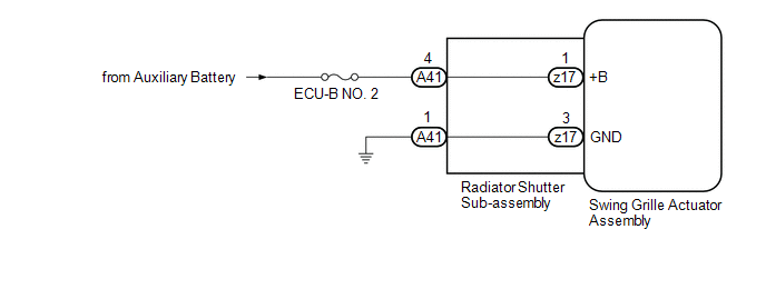
DESCRIPTION
The swing
grille actuator assembly receives signals from the ECM, hybrid vehicle
control ECU assembly and air conditioning amplifier assembly via CAN
communication. Based on these signals, the swing grille actuator
assembly operates the radiator shutter sub-assembly.
WIRING DIAGRAM
CAUTION / NOTICE / HINT
NOTICE:
- Before performing troubleshooting, change the grille shutter control mode to maintenance mode.
Click here 
- If the swing grille actuator assembly has been replaced with a new one,
perform initialization and change the grille shutter control mode.
Click here 
PROCEDURE
|
1. | CHECK FOR FOREIGN OBJECT |
(a) Check that the radiator shutter sub-assembly is free of foreign matter and ice.
OK:
The radiator shutter sub-assembly is free of foreign matter and ice.
| NG |
 | FOREIGN OBJECT (REMOVE FOREIGN MATTER AND/OR ICE) |
|
OK |
 | |
| 2. |
CHECK HARNESS AND CONNECTOR (RADIATOR SHUTTER SUB-ASSEMBLY - POWER SUPPLY AND BODY GROUND) |
| (a) Disconnect the A41 radiator shutter sub-assembly connector. |
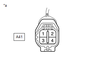 |
|
*a | Front view of wire harness connector
(to Radiator Shutter Sub-assembly) | | |
(b) Measure the voltage according to the value(s) in the table below.
Standard Voltage:
|
Tester Connection | Condition |
Specified Condition |
|
A41-4 - Body ground | Power switch off |
11 to 14 V |
(c) Measure the resistance according to the value(s) in the table below.
Standard Resistance:
|
Tester Connection | Condition |
Specified Condition |
|
A41-1 - Body ground | Always |
Below 1 Ω |
| NG |
 | REPAIR OR REPLACE HARNESS OR CONNECTOR |
|
OK |
 | |
| 3. |
INSPECT RADIATOR SHUTTER SUB-ASSEMBLY |
| (a) Disconnect the z17 radiator shutter sub-assembly connector. |
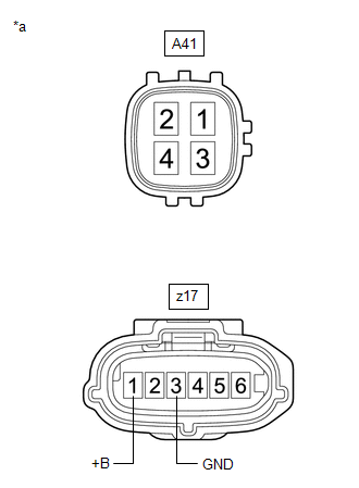 |
|
*a | Component without harness connected
(Radiator Shutter Sub-assembly) | | |
(b) Measure the resistance according to the value(s) in the table below.
Standard Resistance:
|
Tester Connection | Condition |
Specified Condition |
|
A41-4 - z17-1 (+B) | Always |
Below 1 Ω |
|
A41-4 or z17-1 (+B) - Body ground |
Always | 10 kΩ or higher |
|
A41-1 - z17-3 (GND) | Always |
Below 1 Ω |
|
A41-1 or z17-3 (GND) - Body ground |
Always | 10 kΩ or higher |
| NG |
 | REPLACE RADIATOR SHUTTER SUB-ASSEMBLY |
|
OK |
 | |
| 4. |
READ VALUE USING TECHSTREAM |
(a) Connect the Techstream to the DLC3.
(b) Turn the power switch on (IG).
(c) Turn the Techstream on.
(d) Enter the following menus: Body Electrical / Grill Shutter / Active Test.
(e) According to the display on the Techstream, perform the Active Test to open and close the grille shutter.
Body Electrical > Grill Shutter > Active Test
|
Tester Display | Measurement Item |
Control Range | Diagnostic Note |
|
Shutter Closing Operation Lock Detection |
Function to perform a closing operation until motor lock is detected and the motor stops |
OFF/Close | - |
|
Shutter Opening Operation Lock Detection |
Function to perform an opening operation until motor lock is detected and the motor stops |
OFF/Open | - |
Body Electrical > Grill Shutter > Active Test
|
Tester Display |
| Shutter Closing Operation Lock Detection |
Body Electrical > Grill Shutter > Active Test
|
Tester Display |
| Shutter Opening Operation Lock Detection |
(f) Enter the following menus: Body Electrical / Grill Shutter / Data List.
(g) Read the Data List according to the display on the Techstream.
Body Electrical > Grill Shutter > Data List
|
Tester Display | Measurement Item |
Range | Normal Condition |
Diagnostic Note |
|
Shutter Operation Lock Detection Result for Active Test |
Result of Active Test Shutter Closing Operation Lock Detection and Shutter Opening Operation Lock Detection |
Normal, Open Error or Close Error |
Normal: Normal lock detected Open Error: Lock detected in abnormal position while performing Active Test Shutter Opening Operation Lock Detection
Close Error: Lock detected in abnormal position while performing Active Test Shutter Closing Operation Lock Detection |
|
Body Electrical > Grill Shutter > Data List
|
Tester Display |
| Shutter Operation Lock Detection Result for Active Test |
OK:
"Normal" is displayed on the Techstream.
| OK |
 | USE SIMULATION METHOD TO CHECK |
|
NG |
 | |
| 5. |
CHECK RADIATOR SHUTTER SUB-ASSEMBLY |
(a) Remove the radiator shutter sub-assembly.
Click here 
(b) Remove the swing grille actuator assembly.
Click here 
(c) Manually open and close the radiator shutter sub-assembly and check that it moves smoothly.
OK:
The radiator shutter sub-assembly moves smoothly.
| OK |
 | REPLACE SWING GRILLE ACTUATOR ASSEMBLY |
| NG |
 | REPLACE RADIATOR SHUTTER SUB-ASSEMBLY |
How To Proceed With Troubleshooting
CAUTION / NOTICE / HINT
HINT:
- Use the following procedure to troubleshoot the grille shutter system.
- *: Use the Techstream.
PROCEDURE
|
1. | VEHICLE BROUGHT TO WORKSHOP |
|
NEXT |
 | |
| 2. |
CUSTOMER PROBLEM ANALYSIS |
HINT:
- In troubleshooting, confirm that the problem symptoms have been
accurately identified. Preconceptions should be discarded in order to
make an accurate judgment. To clearly understand what the problem
symptoms are, it is extremely important to ask the customer about the
problem and the conditions at the time the malfunction occurred.
- Gather as much information as possible for reference. Past problems that seem unrelated may also help in some cases.
- The following 5 items are important points for problem analysis:
|
What |
Vehicle model, system name |
|
When |
Date, time, occurrence frequency |
|
Where |
Road conditions |
|
Under what conditions? |
Driving conditions, weather conditions |
|
How did it happen? |
Problem symptoms |
|
NEXT |
 | |
(a) Measure the auxiliary battery voltage with the power switch off.
Standard Voltage:
11 to 14 V
If the voltage is below 11 V, recharge or replace the auxiliary battery before proceeding to the next step.
(b) Check the fuses and relays.
(c)
Check the connector connections and terminals to make sure that there
are no abnormalities such as loose connections, deformation, etc.
|
NEXT |
 | |
| 4. |
CHECK COMMUNICATION FUNCTION OF CAN COMMUNICATION SYSTEM* |
(a) Using the Techstream, check for CAN communication system DTCs.
Click here

|
Result | Proceed to |
|
CAN DTCs are not output |
A |
| CAN DTCs are output |
B |
| B |
 | GO TO CAN COMMUNICATION SYSTEM (for HV Model) |
|
A |  | |
| 5. |
CHECK FOR DTC* (SFI SYSTEM) |
(a) Check for DTCs.
Powertrain > Engine > Trouble Codes
|
Result | Proceed to |
|
DTCs are not output | A |
|
DTCs are output | B |
| B |
 | GO TO SFI SYSTEM |
|
A |  | |
| 6. |
CHECK FOR DTC* (GRILLE SHUTTER SYSTEM) |
(a) Check for DTCs.
Body Electrical > Grill Shutter > Trouble Codes
|
Result | Proceed to |
|
DTCs are not output | A |
|
DTCs are output | B |
| B |
 | GO TO DIAGNOSTIC TROUBLE CODE CHART |
|
A |  | |
| 7. |
PROBLEM SYMPTOMS TABLE |
(a) Refer to Problem Symptoms Table.
Click here 
|
Result | Proceed to |
|
Fault is not listed in Problem Symptoms Table |
A |
| Fault is listed in Problem Symptoms Table |
B |
| B |
 | GO TO STEP 9 |
|
A |  | |
| 8. |
OVERALL ANALYSIS AND TROUBLESHOOTING* |
(a) Terminals of ECU
Click here 
(b) Data List / Active Test
Click here 
|
NEXT |
 | |
|
NEXT |
 | |
| 10. |
CHECK FOR DTC* (GRILLE SHUTTER SYSTEM) |
(a) Check for DTCs.
Body Electrical > Grill Shutter > Trouble Codes
|
Result | Proceed to |
|
DTCs are not output | A |
|
DTCs are output | B |
| A |
 | END |
| B |
 | GO TO DIAGNOSTIC TROUBLE CODE CHART |
Initialization
INITIALIZATION
CHANGE GRILLE SHUTTER CONTROL MODE AND/OR PERFORM INITIALIZATION
(a)
In the following situations, it is necessary to change the grille
shutter control mode and/or initialize the grille shutter system.
| |
Change Control Mode (Normal Mode → Maintenance Mode) |
Change Control Mode (Maintenance Mode → Normal Mode) |
Initialize |
| Before removing the swing grille actuator assembly and radiator shutter sub-assembly |
â—‹ | - |
- |
| When the swing grille actuator assembly has been replaced with a new one |
- | â—‹ |
â—‹ |
| After installing the swing grille actuator assembly and radiator shutter sub-assembly |
- | â—‹ |
â—‹ |
| Before troubleshooting |
â—‹ | - |
- |
| After troubleshooting |
- | â—‹ |
- |
NOTICE:
In
order to ensure safety, before performing troubleshooting or removing
the swing grille actuator assembly or radiator shutter sub-assembly,
change the grille shutter control mode to maintenance mode.
HINT:
- When the grille shutter system is in maintenance mode, the grille shutter will not operate when operation signals are received.
- When driving the vehicle to change the grille shutter control mode
and/or perform initialization, make sure the grille shutter system is in
maintenance mode. Initialization cannot be performed and the grille
shutter control mode cannot be changed by driving the vehicle if the
grille shutter system is in normal mode.
WHEN USING TECHSTREAM
(a) Change the control mode to maintenance mode.
(1) Connect the Techstream to the DLC3.
(2) Turn the power switch on (IG).
(3) Turn the Techstream on.
(4) Enter following menus: Body Electrical / Grill Shutter / Utility.
Body Electrical > Grill Shutter > Utility
|
Tester Display |
| Grill Shutter Control Mode Switching |
(5) According to the display on the Techstream, change the grille shutter control mode from normal mode to maintenance mode.
(b) Change the control mode to normal mode
(1) Connect the Techstream to the DLC3.
(2) Turn the power switch on (IG).
(3) Turn the Techstream on.
(4) Enter following menus: Body Electrical / Grill Shutter / Utility.
Body Electrical > Grill Shutter > Utility
|
Tester Display |
| Grill Shutter Control Mode Switching |
(5) According to the display on the Techstream, change the grille shutter control mode from maintenance mode to normal mode.
(6) Check for DTCs and make sure that DTC B1333 is not output.
Body Electrical > Grill Shutter > Trouble Codes
(c) Initialize
(1) Connect the Techstream to the DLC3.
(2) Turn the power switch on (IG).
(3) Turn the Techstream on.
(4) Enter following menus: Body Electrical / Grill Shutter / Utility.
Body Electrical > Grill Shutter > Utility
|
Tester Display |
| Grill Shutter Initialization |
(5) According to the display on the Techstream, perform initialization.
WHEN DRIVING THE VEHICLE
HINT:
When
changing the grille shutter control mode and/or performing
initialization by driving the vehicle, the grille shutter control mode
can only be changed and initialization can only be performed if the
grille shutter system is in maintenance mode.
(a) Turn the power switch on (READY).
(b)
Drive the vehicle at speed of 5 km/h (3 mph) or more. The grille
shutter control mode will be changed and initialization will be
performed automatically when the vehicle speed exceeds 5 km/h (3 mph).
(c) Check for DTCs and make sure that DTC B1333 is not output.
Body Electrical > Grill Shutter > Trouble CodesParts Location
PARTS LOCATION
ILLUSTRATION
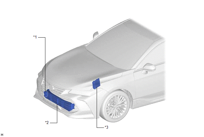
|
*1 | SWING GRILLE ACTUATOR ASSEMBLY |
*2 | RADIATOR SHUTTER SUB-ASSEMBLY |
|
*3 | ECM |
- | - |
ILLUSTRATION
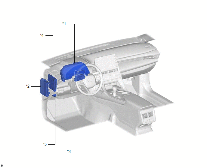
|
*1 | COMBINATION METER ASSEMBLY |
*2 | INSTRUMENT PANEL JUNCTION BLOCK ASSEMBLY
- ECU-B NO. 2 FUSE |
|
*3 | AIR CONDITIONING AMPLIFIER ASSEMBLY |
*4 | HYBRID VEHICLE CONTROL ECU ASSEMBLY |
|
*5 | DLC3 |
- | - |
Precaution
PRECAUTION
PRECAUTION FOR DISCONNECTING CABLE FROM NEGATIVE AUXILIARY BATTERY TERMINAL
NOTICE:
When
disconnecting the cable from the negative (-) auxiliary battery
terminal, initialize the following systems after the cable is
reconnected.
|
System Name | See Procedure |
|
Lane Departure Alert System (w/ Steering Control) |
 |
|
Intelligent Clearance Sonar System |
|
Parking Assist Monitor System |
|
Panoramic View Monitor System |
|
Pre-collision System |
| Lighting System (for HV Model with Cornering Light) |
Problem Symptoms Table
PROBLEM SYMPTOMS TABLE
NOTICE:
- Before performing troubleshooting, change the grille shutter control mode to maintenance mode.
Click here 
- If the swing grille actuator assembly has been replaced with a new one,
perform initialization and change the grille shutter control mode.
Click here 
HINT:
- Use the table below to help determine the cause of problem symptoms. If
multiple suspected areas are listed, the potential causes of the
symptoms are listed in order of probability in the "Suspected Area"
column of the table. Check each symptom by checking the suspected areas
in the order they are listed. Replace parts as necessary.
- Inspect the fuses and relays related to this system before inspecting the suspected areas below.
|
Symptom | Suspected Area |
Link |
| Grille shutter does not operate |
Proceed to "Grille Shutter does not Operate" |
 |
|
Abnormal noise occurs during grille shutter operation |
Check for ice, etc. around the shutters and links |
- |
| Swing grille actuator assembly |
 |
|
Radiator shutter sub-assembly |
 |
System Description
SYSTEM DESCRIPTION
GRILLE SHUTTER SYSTEM
(a) General description
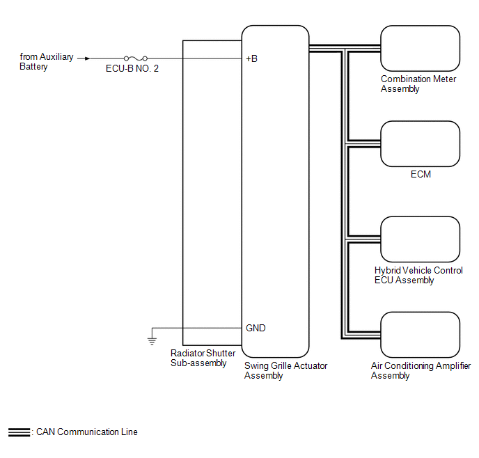
The
swing grille actuator assembly receives signals from the ECM, hybrid
vehicle control ECU assembly and air conditioning amplifier assembly via
CAN communication. Based on these signals, the swing grille actuator
assembly operates the radiator shutter sub-assembly.
If
a malfunction occurs in the grille shutter system, a warning will be
displayed on the multi-information display and grille shutter system
operation will be disabled.
(b) Control List
|
Control | Description |
|
Closing Operation Control | The
grille shutter closes when certain conditions related to the vehicle
speed, engine coolant temperature, inverter coolant temperature, ambient
temperature and refrigerant pressure are met. |
|
Opening Operation Control | The
grille shutter opens when certain conditions related to the vehicle
speed, engine coolant temperature, inverter coolant temperature, ambient
temperature and refrigerant pressure are met. |
|
Power Switch Off-linked Opening Operation Control |
Opens
the grille shutter when the power switch is turned off in order to
prevent the grille shutter from becoming stuck closed while the vehicle
is stopped. |
| Winter Control Mode |
Stops
the grille shutter at a position other than the fully closed position
and suspends grille shutter operation in order to prevent it from
becoming stuck closed when the ambient temperature is 5°C (41°F) or
lower. Winter control mode is canceled when the ambient temperature
becomes 10°C (50°F) or higher. |
System Diagram
SYSTEM DIAGRAM
Terminals Of Ecu
TERMINALS OF ECU

CHECK SWING GRILLE ACTUATOR ASSEMBLY
(a) Disconnect the z17 swing grille actuator assembly connector.
(b) Measure the voltage and resistance according to the value(s) in the table below.
HINT:
Measure the values on the wire harness side with the connector disconnected.
|
Tester Connection | Wiring Color |
Terminal Description | Condition |
Specified Condition |
|
z17-1 (+B) - Body ground |
LA-G - Body ground | Auxiliary battery power supply |
Power switch off | 11 to 14 V |
|
z17-3 (GND) - Body ground |
W-B - Body ground | Ground |
Always | Below 1 Ω |


