Components
COMPONENTS
ILLUSTRATION
|
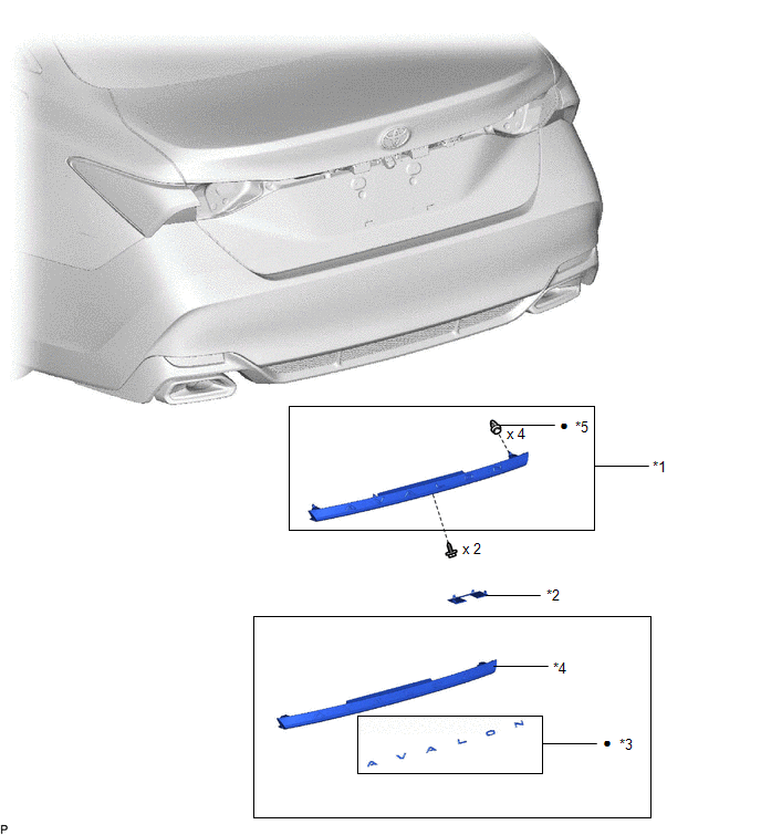
*1 | LUGGAGE COMPARTMENT DOOR OUTSIDE GARNISH SUB-ASSEMBLY |
*2 | NO. 2 BACK DOOR OUTSIDE GARNISH |
|
*3 | NO. 2 LUGGAGE COMPARTMENT DOOR NAME PLATE |
*4 | LUGGAGE COMPARTMENT DOOR OUTSIDE GARNISH |
|
*5 | CLIP |
- | - |
|
â—Ź | Non-reusable part |
- | - |
Disassembly
DISASSEMBLY
PROCEDURE
1. REMOVE NO. 2 LUGGAGE COMPARTMENT DOOR NAME PLATE
Click here

Installation
INSTALLATION
PROCEDURE
1. INSTALL LUGGAGE COMPARTMENT DOOR OUTSIDE GARNISH SUB-ASSEMBLY
(a) Install 4 new clips to the luggage compartment door outside garnish.
(b) Engage the 4 clips as shown in the illustration.
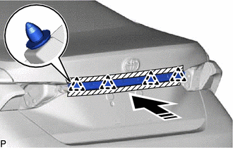
 |
Install in this Direction |
(c) Install the luggage compartment door outside garnish sub-assembly with the 2 screws.
2. INSTALL NO. 2 BACK DOOR OUTSIDE GARNISH
| (a) Engage the 4 claws to install the No. 2 back door outside garnish. |
|
3. INSTALL REAR LIGHT ASSEMBLY LH
Click here

4. INSTALL REAR LIGHT ASSEMBLY RH
HINT:
Use the same procedure as for the LH side.
Reassembly
REASSEMBLY
PROCEDURE
1. INSTALL NO. 2 LUGGAGE COMPARTMENT DOOR NAME PLATE
Click here

Removal
REMOVAL
PROCEDURE
1. REMOVE REAR LIGHT ASSEMBLY LH
Click here

2. REMOVE REAR LIGHT ASSEMBLY RH
HINT:
Use the same procedure as for the LH side.
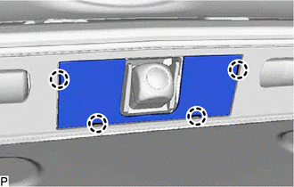
3. REMOVE NO. 2 BACK DOOR OUTSIDE GARNISH
| (a) Using a screwdriver with its tip wrapped with protective tape, disengage the 4 claws to remove the No. 2 back door outside garnish. |
|
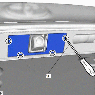
4. REMOVE LUGGAGE COMPARTMENT DOOR OUTSIDE GARNISH SUB-ASSEMBLY
(a) Apply protective tape around the luggage compartment door outside garnish sub-assembly.
 | Protective Tape |
| (b) Remove the 2 screws. |
|
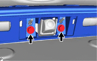
(c) Using a moulding remover, disengage the 4 clips and remove the luggage compartment door outside garnish sub-assembly as shown in the illustration.
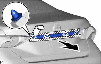
 |
Remove in this Direction |
(d) Remove the 4 clips from the luggage compartment door outside garnish.
Toyota Avalon (XX50) 2019-2022 Service & Repair Manual > Door / Hatch: Fuel Lid Opener Switch
Components COMPONENTS ILLUSTRATION *1 COWL SIDE TRIM SUB-ASSEMBLY LH *2 FRONT DOOR OPENING TRIM WEATHERSTRIP LH *3 FRONT DOOR SCUFF PLATE LH *4 FUEL LID OPENER SWITCH *5 HOOD LOCK CONTROL LEVER SUB-ASSEMBLY *6 INSTRUMENT SIDE PANEL LH *7 NO. 1 INSTRUMENT PANEL SUB-ASSEMBLY *8 NO. 1 INSTRUMENT PANEL ...