Components
COMPONENTS
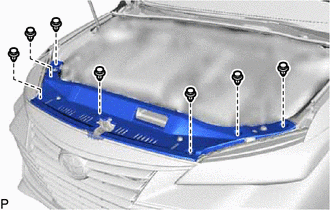
ILLUSTRATION
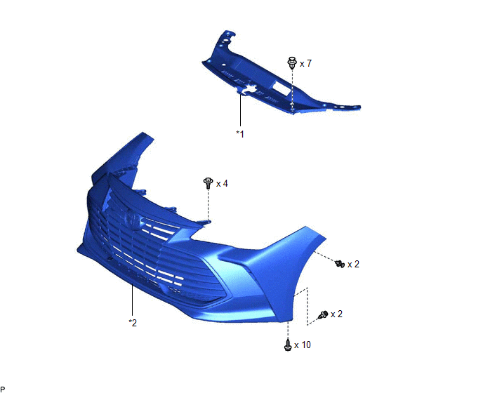
|
*1 | COOL AIR INTAKE DUCT SEAL |
*2 | FRONT BUMPER ASSEMBLY |
ILLUSTRATION
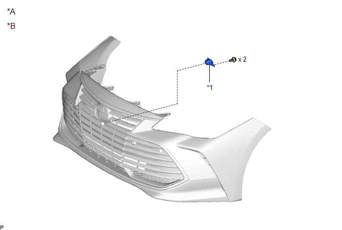
|
*A | w/ Panoramic View Monitor System |
*B | for Bar Type Radiator Grille |
|
*1 | FRONT TELEVISION CAMERA ASSEMBLY |
- | - |
ILLUSTRATION
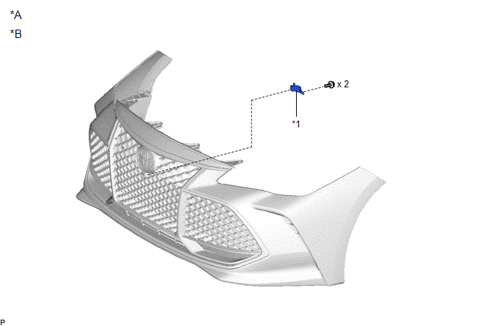
|
*A | w/ Panoramic View Monitor System |
*B | for Mesh Type Radiator Grille |
|
*1 | FRONT TELEVISION CAMERA ASSEMBLY |
- | - |
ILLUSTRATION
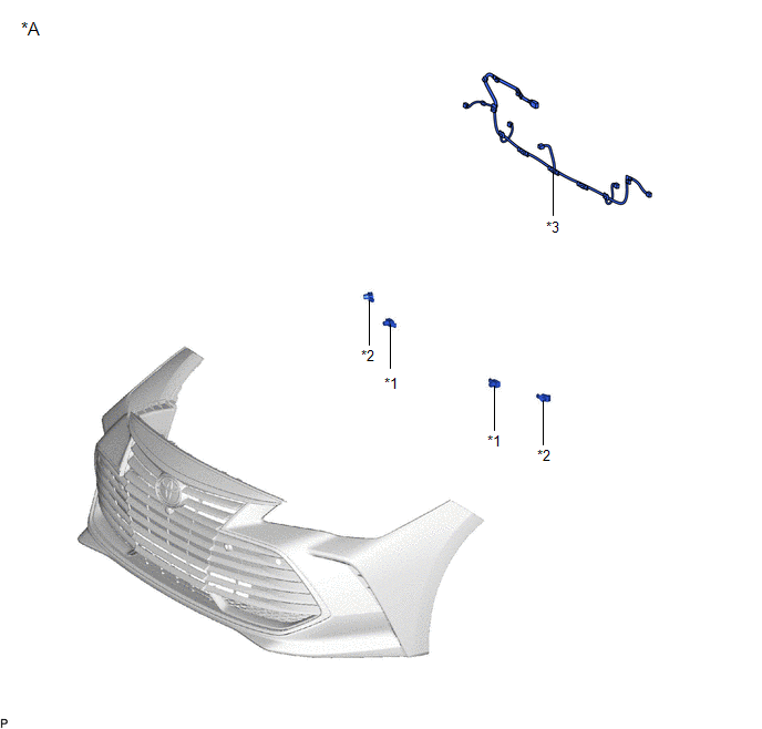
|
*A | w/ Intuitive Parking Assist System |
- | - |
|
*1 | FRONT CENTER ULTRASONIC SENSOR |
*2 | FRONT CORNER ULTRASONIC SENSOR |
|
*3 | NO. 4 ENGINE ROOM WIRE |
- | - |
ILLUSTRATION
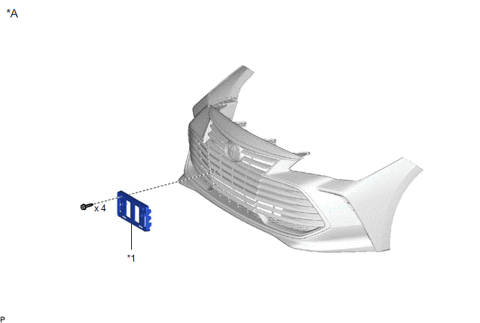
|
*A | for Bar Type Radiator Grille |
- | - |
|
*1 | FRONT LICENSE PLATE BRACKET SUB-ASSEMBLY |
- | - |
ILLUSTRATION
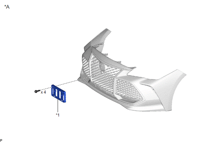
|
*A | for Mesh Type Radiator Grille |
- | - |
|
*1 | FRONT LICENSE PLATE BRACKET SUB-ASSEMBLY |
- | - |
ILLUSTRATION
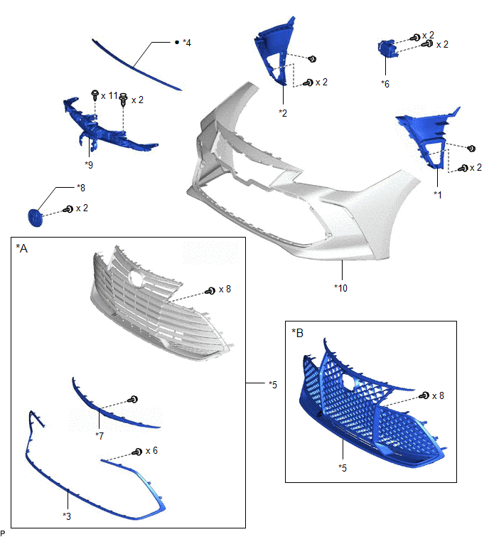
|
*A | for Bar Type Radiator Grille |
*B | for Mesh Type Radiator Grille |
|
*1 | AIR INTAKE DUCT LH |
*2 | AIR INTAKE DUCT RH |
|
*3 | FRONT BUMPER MOULDING |
*4 | HOOD TO FRONT END PANEL SEAL |
|
*5 | LOWER RADIATOR GRILLE SUB-ASSEMBLY |
*6 | MILLIMETER WAVE RADAR SENSOR ASSEMBLY |
|
*7 | RADIATOR GRILLE |
*8 | RADIATOR GRILLE EMBLEM ASSEMBLY |
|
*9 | RADIATOR GRILLE SUB-ASSEMBLY |
*10 | FRONT BUMPER COVER |
|
â—Ź | Non-reusable part |
- | - |
ILLUSTRATION
|
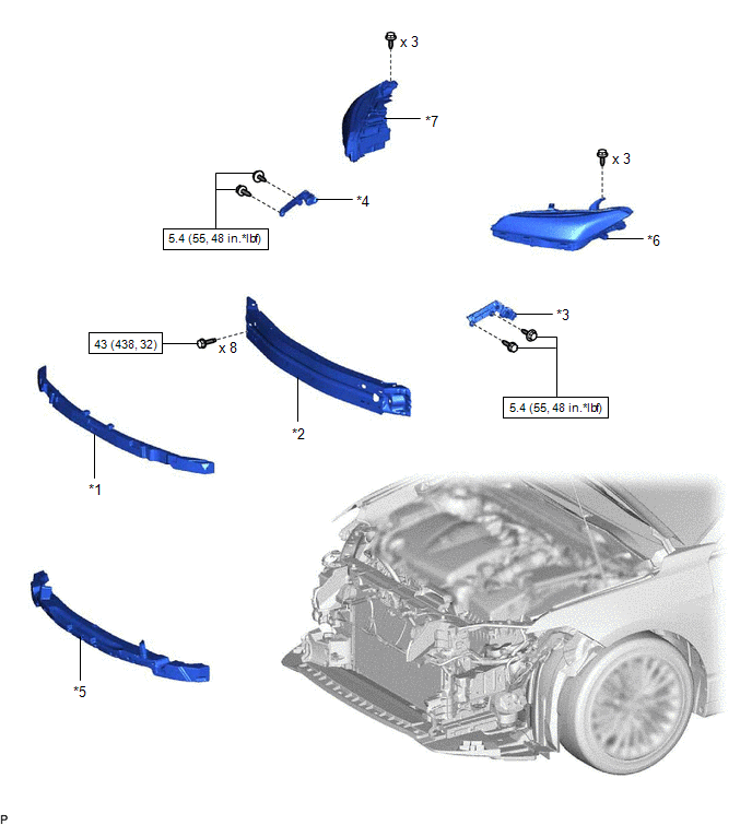
*1 | FRONT BUMPER ENERGY ABSORBER |
*2 | FRONT BUMPER REINFORCEMENT |
|
*3 | FRONT BUMPER SIDE RETAINER LH |
*4 | FRONT BUMPER SIDE RETAINER RH |
|
*5 | NO. 2 FRONT BUMPER ENERGY ABSORBER |
*6 | HEADLIGHT ASSEMBLY LH |
|
*7 | HEADLIGHT ASSEMBLY RH |
- | - |
 |
N*m (kgf*cm, ft.*lbf): Specified torque |
- | - |
Disassembly
DISASSEMBLY
PROCEDURE
1. REMOVE FRONT TELEVISION CAMERA ASSEMBLY (w/ Panoramic View Monitor System)
Click here 
2. REMOVE FRONT CENTER ULTRASONIC SENSOR (w/ Intuitive Parking Assist System)
Click here 
HINT:
Use the same procedure for the RH side and LH side.
3. REMOVE FRONT CORNER ULTRASONIC SENSOR (w/ Intuitive Parking Assist System)
Click here 
HINT:
Use the same procedure for the RH side and LH side.
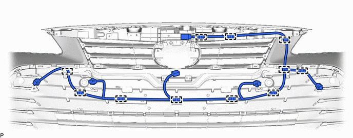
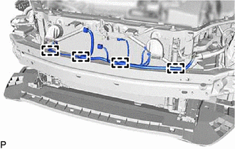
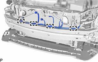
4. REMOVE NO. 4 ENGINE ROOM WIRE (w/ Intuitive Parking Assist System)
(a) Disengage the 11 clamps to remove the No. 4 engine room wire.
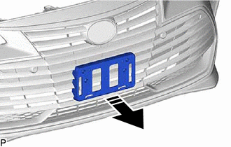
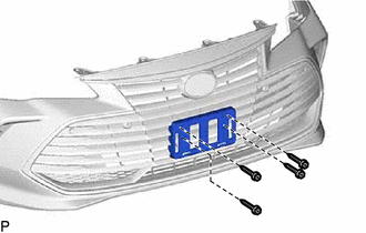
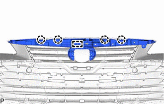
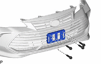
5. REMOVE FRONT LICENSE PLATE BRACKET SUB-ASSEMBLY (for Bar Type Radiator Grille)
(b) Remove the front licence plate bracket sub-assembly as shown in the illustration.
 |
Remove in this Direction |
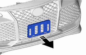
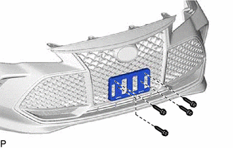
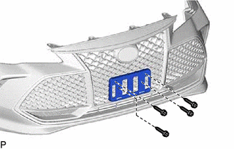
6. REMOVE FRONT LICENSE PLATE BRACKET SUB-ASSEMBLY (for Mesh Type Radiator Grille)
(b) Remove the front licence plate bracket sub-assembly as shown in the illustration.
 |
Remove in this Direction |
7. REMOVE AIR INTAKE DUCT LH
(a) Remove the 2 screws and clip.
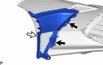
 |
Screw |
 |
Clip |
(b) Disengage the 4 guides to remove the air intake duct LH as shown in the illustration.
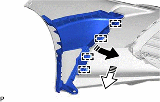
 |
Remove in this Direction (1) |
 |
Remove in this Direction (2) |
8. REMOVE AIR INTAKE DUCT RH
HINT:
Use the same procedure as for the LH side.
9. REMOVE MILLIMETER WAVE RADAR SENSOR ASSEMBLY
Click here 
10. REMOVE HOOD TO FRONT END PANEL SEAL
(a) Disengage the 4 clips.
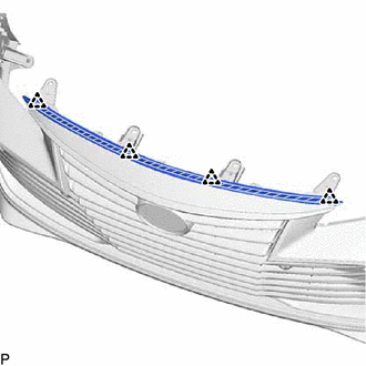
 |
Double-sided Tape |
(b) Separate the double-sided tape and remove the hood to front end panel seal.
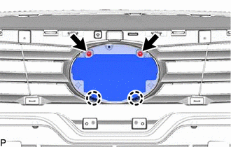
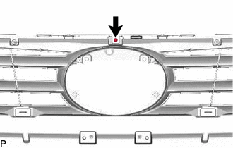
11. REMOVE RADIATOR GRILLE EMBLEM ASSEMBLY
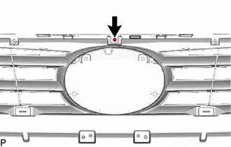
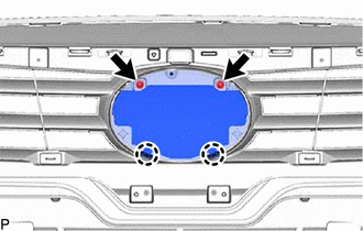
(b) Disengage the 2 claws to remove the radiator grille emblem assembly.
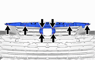
12. REMOVE RADIATOR GRILLE SUB-ASSEMBLY
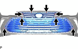
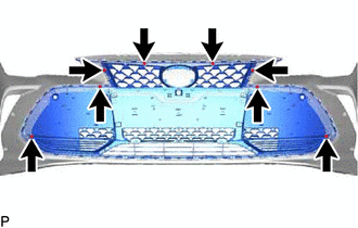
(a) Remove the 3 screws and 2 clips.
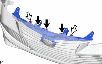
 |
Screw |
 |
Clip |
| (c) Disengage the 4 claws and guide to remove the radiator grille sub-assembly. |
|
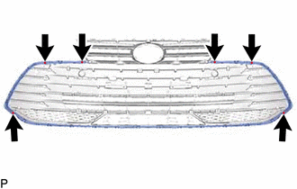
13. REMOVE LOWER RADIATOR GRILLE SUB-ASSEMBLY (for Bar Type Radiator Grille)
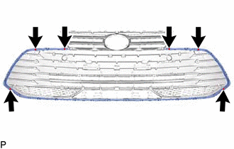
(b) Disengage the 23 claws and 5 guides to remove the lower radiator grille sub-assembly.
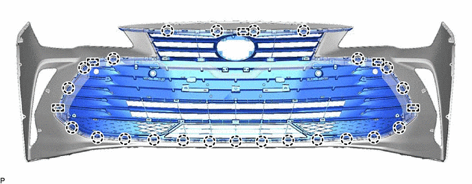
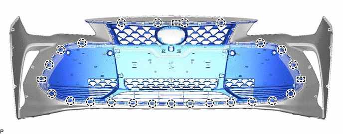
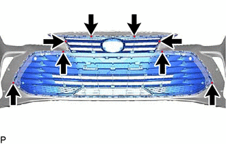
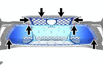
14. REMOVE LOWER RADIATOR GRILLE SUB-ASSEMBLY (for Mesh Type Radiator Grille)
(b) Disengage the 23 claws and 3 guides to remove the lower radiator grille sub-assembly.
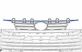
15. REMOVE RADIATOR GRILLE (for Bar Type Radiator Grille)
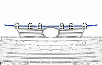
| (b) Disengage the 6 claws and 6 guides to remove the radiator grille. |
|
16. REMOVE FRONT BUMPER MOULDING (for Bar Type Radiator Grille)
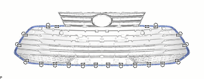
(b) Disengage the 18 claws and 20 guides to remove the front bumper moulding.
17. REMOVE FRONT BUMPER SIDE RETAINER LH
(a) Remove the bolt (A) and bolt (B).
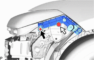
 |
Bolt (A) |
 |
Bolt (B) |
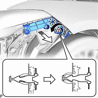
(b) Disengage the clip as shown in the illustration.
 |
Remove in this Direction (1) |
 |
Remove in this Direction (2) |
(c) Disengage the claw to remove the front bumper side retainer LH as shown in the illustration.
18. REMOVE FRONT BUMPER SIDE RETAINER RH
HINT:
Use the same procedure as for the LH side.
19. REMOVE NO. 2 FRONT BUMPER ENERGY ABSORBER
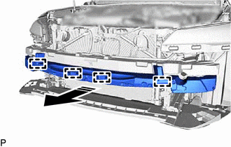
(a) Disengage the 4 guides to remove the No. 2 front bumper energy absorber as shown in the illustration.
 |
Remove in this Direction |
20. REMOVE FRONT BUMPER ENERGY ABSORBER
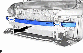
(a) Disengage the 2 guides to remove the front bumper energy absorber as shown in the illustration.
 |
Remove in this Direction |
21. REMOVE FRONT BUMPER REINFORCEMENT
(a) Remove the headlight assembly LH.
Click here

(b) Remove the headlight assembly RH.
HINT:
Use the same procedure as for the LH side.
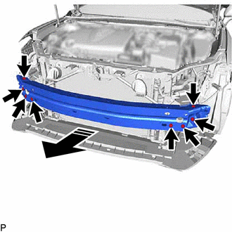
| (c) Disengage the 4 clamps. | |
(d) Remove the 8 bolts and front bumper reinforcement as shown in the illustration.
 |
Remove in this Direction |
Installation
INSTALLATION
CAUTION / NOTICE / HINT
HINT:
If
the front bumper has been damaged or deformed due to an accident or
contact with an object, etc., or the bumper installation area of the
vehicle body has been repaired, it is necessary to perform millimeter
wave radar sensor adjustment.
Click here 
PROCEDURE
1. INSTALL FRONT BUMPER ASSEMBLY
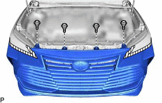
(a) Move the front bumper assembly into position and engage the 2 guides as shown in the illustration.
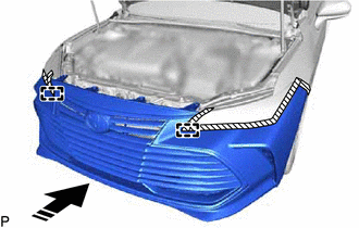
 |
Install in this Direction |
(b) Install the 4 bolts.
(c) w/ Intuitive Parking Assist System:
(1) Connect the connector.
(d) Connect the connector.
(e) Engage the 4 claws as shown in the illustration.
HINT:
Use the same procedure for the RH side and LH side.
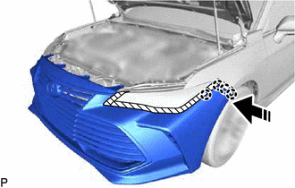
 |
Install in this Direction |
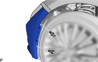
(f) Install the 8 screws.
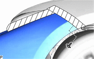
(g) Install the screw.
HINT:
Use the same procedure for the RH side and LH side.
(h) Install the front bumper assembly with the 2 clips.
HINT:
Use the same procedure for the RH side and LH side.
2. INSTALL COOL AIR INTAKE DUCT SEAL
(a) Engage the guide as shown in the illustration.
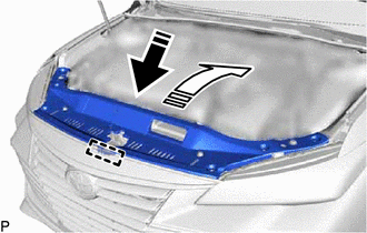
 |
Install in this Direction (1) |
 |
Install in this Direction (2) |
(b) Install the cool air intake duct seal with the 7 clips.
3. ADJUST FRONT TELEVISION CAMERA ASSEMBLY (w/ Panoramic View Monitor System)
for HV Model:
Click here 
for Gasoline Model:
Click here 
4. PERFORM CALIBRATION (w/ Intelligent Clearance Sonar System)
for HV Model:
Click here 
for Gasoline Model:
Click here 
5. ADJUST HEADLIGHT AIMING
HINT:
Perform this procedure only when the front bumper reinforcement has been replaced.
Click here 
Reassembly
REASSEMBLY
PROCEDURE
1. INSTALL FRONT BUMPER REINFORCEMENT
(a) Install the front bumper reinforcement with the 8 bolts.
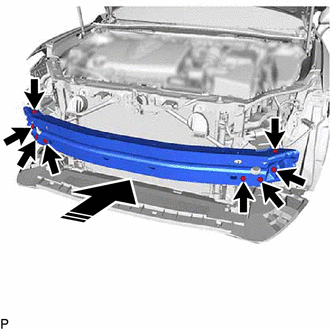
 |
Install in this Direction |
Torque:
43 N·m {438 kgf·cm, 32 ft·lbf}
(c) Install the headlight assembly LH.
Click here

(d) Install the headlight assembly RH.
HINT:
Use the same procedure as for the LH side.
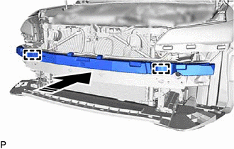
2. INSTALL FRONT BUMPER ENERGY ABSORBER
(a) Engage the 2 guides to install the front bumper energy absorber as shown in the illustration.
 |
Install in this Direction |
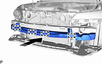
3. INSTALL NO. 2 FRONT BUMPER ENERGY ABSORBER
(a) Engage the 4 guides to install the No. 2 front bumper energy absorber as shown in the illustration.
 |
Install in this Direction |
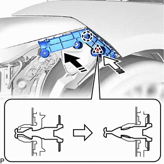
4. INSTALL FRONT BUMPER SIDE RETAINER LH
(a) Engage the claw to temporarily install the front bumper side retainer LH as shown in the illustration.
 |
Install in this Direction (1) |
 |
Install in this Direction (2) |
(b) Engage the clip as shown in the illustration.
(c) Install the front bumper side retainer LH with the bolt (A) and bolt (B).
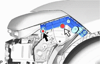
 |
Bolt (A) |
 |
Bolt (B) |
Torque:
5.4 N·m {55 kgf·cm, 48 in·lbf}
5. INSTALL FRONT BUMPER SIDE RETAINER RH
HINT:
Use the same procedure as for the LH side.
6. INSTALL FRONT BUMPER MOULDING (for Bar Type Radiator Grille)
(a) Engage the 20 guides and 18 claws.
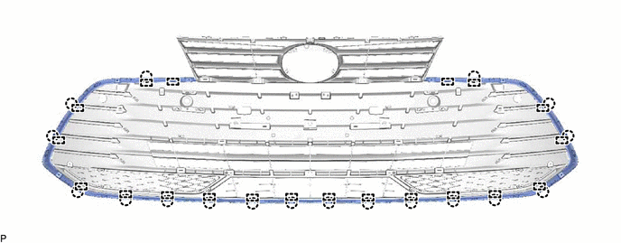
| (b) Install the front bumper moulding with the 6 screws. |
|
7. INSTALL RADIATOR GRILLE (for Bar Type Radiator Grille)
| (a) Engage the 6 guides and 6 claws. | |
| (b) Install the radiator grille with the screw. | |
8. INSTALL LOWER RADIATOR GRILLE SUB-ASSEMBLY (for Bar Type Radiator Grille)
(a) Engage the 5 guides and 23 claws.
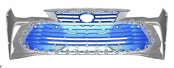
| (b) Install the lower radiator grille sub-assembly with the 8 screws. |
|
9. INSTALL LOWER RADIATOR GRILLE SUB-ASSEMBLY (for Mesh Type Radiator Grille)
(a) Engage the 3 guides and 23 claws.
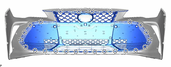
| (b) Install the lower radiator grille sub-assembly with the 8 screws. |
|
10. INSTALL RADIATOR GRILLE SUB-ASSEMBLY
| (a) Engage the guide and 4 claws. | |
| (b) Install the 8 screws. | |
(c) Install the radiator grille sub-assembly with the 2 clips and 3 screws.
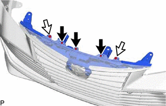
 |
Screw |
 |
Clip |
11. INSTALL RADIATOR GRILLE EMBLEM ASSEMBLY
(b) Install the radiator grille emblem assembly with the 2 screws.
12. INSTALL HOOD TO FRONT END PANEL SEAL
HINT:
When installing the hood to front end panel seal, heat the front bumper cover using a heat light.
Heating Temperature |
Item | Temperature |
|
Front Bumper Cover | 20 to 30°C (68 to 86°F) |
CAUTION:
- Do not touch the heat light and heated parts, touching the heat light may result in burns.
- Touching heated parts for a long time may result in burns.
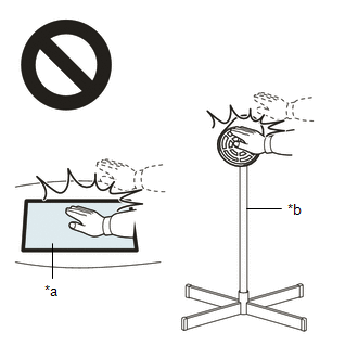
|
*a | Heated Part |
|
*b | Heat Light |
NOTICE:
Do not heat the front bumper cover excessively.
(a) Clean the front bumper cover surface.
(1) Using a heat light, heat the front bumper cover surface.
(2) Remove any remaining double-sided tape from the front bumper cover.
(3) Wipe off any tape adhesive residue with cleaner.
(b) Remove the release paper from a new hood to front end panel seal.
HINT:
After removing the release paper, keep the exposed adhesive free from foreign matter.
(c) Attach the double-sided tape as shown in the illustration.
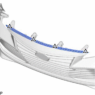
 |
Double-sided Tape |
HINT:
Press the hood to front end panel seal firmly to install it.
(d) Engage the 4 clips to install the hood to front end panel seal.
13. INSTALL MILLIMETER WAVE RADAR SENSOR ASSEMBLY
Click here 
14. INSTALL AIR INTAKE DUCT LH
(a) Engage the 4 guides as shown in the illustration.
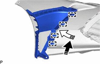
 |
Install in this Direction (1) |
 |
Install in this Direction (2) |
(b) Install the air intake duct LH with the clip and 2 screws.
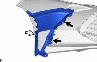
 |
Screw |
 |
Clip |
15. INSTALL AIR INTAKE DUCT RH
HINT:
Use the same procedure as for the LH side.
16. INSTALL FRONT LICENSE PLATE BRACKET SUB-ASSEMBLY (for Bar Type Radiator Grille)
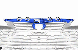
(a) Temporarily install the front license plate bracket sub-assembly as shown in the illustration.
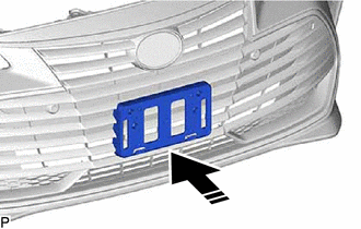
 |
Install in this Direction |
| (b) Install the front license plate bracket sub-assembly with the 4 screws. |
|
17. INSTALL FRONT LICENSE PLATE BRACKET SUB-ASSEMBLY (for Mesh Type Radiator Grille)
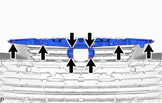
(a) Temporarily install the front license plate bracket sub-assembly as shown in the illustration.
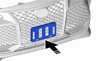
 |
Install in this Direction |
| (b) Install the front license plate bracket sub-assembly with the 4 screws. |
|
18. INSTALL NO. 4 ENGINE ROOM WIRE (w/ Intuitive Parking Assist System)
(a) Engage the 11 clamps to install the No. 4 engine room wire.
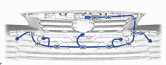
19. INSTALL FRONT CORNER ULTRASONIC SENSOR (w/ Intuitive Parking Assist System)
Click here 
HINT:
Use the same procedure for the RH side and LH side.
20. INSTALL FRONT CENTER ULTRASONIC SENSOR (w/ Intuitive Parking Assist System)
Click here 
HINT:
Use the same procedure for the RH side and LH side.
21. INSTALL FRONT TELEVISION CAMERA ASSEMBLY (w/ Panoramic View Monitor System)
Click here 
Removal
REMOVAL
CAUTION / NOTICE / HINT
The
necessary procedures (adjustment, calibration, initialization, or
registration) that must be performed after parts are removed and
installed, or replaced during front bumper assembly removal/installation
are shown below.
Necessary Procedure After Parts Removed/Installed/Replaced (for Gasoline Model) |
Replaced Part or Performed Procedure |
Necessary Procedure | Effect/Inoperative Function when Necessary Procedure not Performed |
Link |
|
*: Applies only for when removing and installing or replacing the television camera assembly.
|
| Front television camera assembly, front bumper assembly or radiator grille |
- Television camera view adjustment
- Television camera assembly optical axis adjustment (Back camera position setting)*
| Panoramic View Monitor System |
 for Initialization for Initialization
 for Calibration for Calibration |
|
Front bumper assembly |
- Measurement of ultrasonic sensor detection angle
- Ultrasonic sensor detection angle registration
|
- Intelligent Clearance Sonar System
- Intuitive Parking Assist System
|
 |
Necessary Procedure After Parts Removed/Installed/Replaced (for HV Model) |
Replaced Part or Performed Procedure |
Necessary Procedure | Effect/Inoperative Function when Necessary Procedure not Performed |
Link |
|
*: Applies only for when removing and installing or replacing the television camera assembly.
|
| Front television camera assembly, front bumper assembly or radiator grille |
- Television camera view adjustment
- Television camera assembly optical axis adjustment (Back camera position setting)*
| Panoramic View Monitor System |
 for Initialization for Initialization
 for Calibration for Calibration |
|
Front bumper assembly |
- Measurement of ultrasonic sensor detection angle
- Ultrasonic sensor detection angle registration
|
- Intelligent Clearance Sonar System
- Intuitive Parking Assist System
|
 |
HINT:
If
the front bumper has been damaged or deformed due to an accident or
contact with an object, etc., or the bumper installation area of the
vehicle body has been repaired, it is necessary to perform millimeter
wave radar sensor adjustment.
Click here 
PROCEDURE
1. REMOVE COOL AIR INTAKE DUCT SEAL
(b) Disengage the guide and remove the cool air intake duct seal as shown in the illustration.
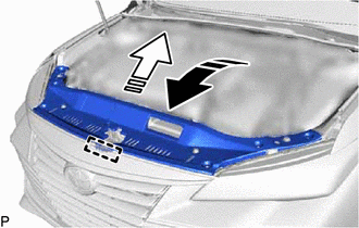
 |
Remove in this Direction (1) |
 |
Remove in this Direction (2) |
2. REMOVE FRONT BUMPER ASSEMBLY
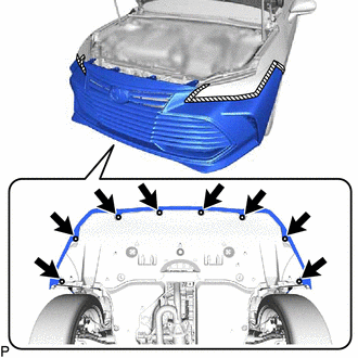
(a) Apply protective tape around the front bumper assembly as shown in the illustration.
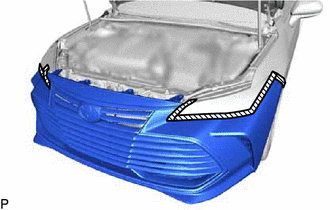
 | Protective Tape |
| (b) Remove the 2 clips. HINT: Use the same procedure for the RH side and LH side. |
|
| (c) Remove the screw. HINT: Use the same procedure for the RH side and LH side. |
|
(e) Disengage the 4 claws as shown in the illustration.
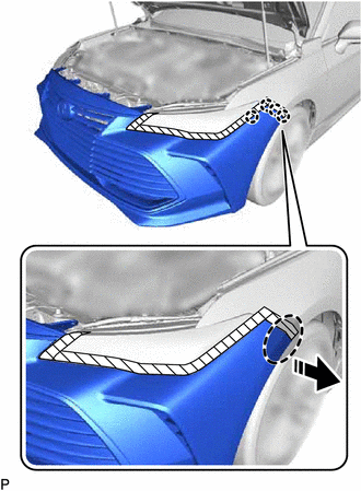
 |
Place Hand Here |
 |
Remove in this Direction |
HINT:
Use the same procedure for the RH side and LH side.
| (f) Disconnect the connector. |
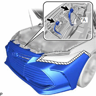 |
|
*A | w/ Intuitive Parking Assist System | | |
(g) w/ Intuitive Parking Assist System:
(1) Disconnect the connector.
(i) Disengage the 2 guides to remove the front bumper assembly as shown in the illustration.
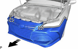
 |
Remove in this Direction |


























 for Initialization
 for Calibration
 for Initialization
 for Calibration

