Adjustment
ADJUSTMENT
CAUTION / NOTICE / HINT
|
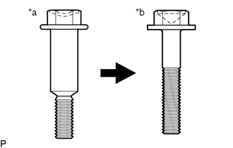
*a | Centering Bolt |
|
*b | Standard Bolt |
HINT:
- Centering bolts are used to mount the door hinge to the door. The door
cannot be adjusted with the centering bolts installed. Substitute the
centering bolts with standard bolts when making adjustments.
- Specified torque for standard bolts is shown in the standard bolt chart.
Click here 
PROCEDURE
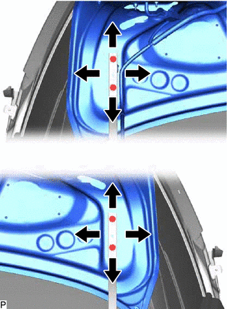
1. INSPECT LUGGAGE COMPARTMENT DOOR
(a) Check that the clearance measurements of areas a through j are within each standard range.
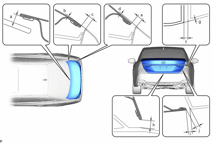 Standard Clearance
 |
Area | Measurement |
Area | Measurement |
|
a | 5.95 mm (0.234 in.) |
b | -1.3 to 1.4 mm (-0.0512 to 0.0551 in.) |
|
c | 2.4 to 5.1 mm (0.0945 to 0.200 in.) |
d | -0.95 to 1.75 mm (-0.0374 to 0.0689 in.) |
|
e | 3.2 to 5.9 mm (0.126 to 0.232 in.) |
f | 2.5 to 6.5 mm (0.0984 to 0.256 in.) |
|
g | -2.0 to 2.0 mm (-0.0787 to 0.0787 in.) |
h | 3.85 to 7.85 mm (0.152 to 0.309 in.) |
|
i | 1.95 to 5.95 mm (0.0768 to 0.234 in.) |
j | 2.35 to 6.35 mm (0.0925 to 0.250 in.) |
2. REMOVE SPARE WHEEL COVER ASSEMBLY
Click here
3. REMOVE BAGGAGE HOLDER NET
Click here
4. REMOVE NO. 1 LUGGAGE COMPARTMENT TRIM HOOK
Click here
5. REMOVE REAR FLOOR FINISH PLATE
Click here
6. REMOVE LUGGAGE COMPARTMENT DOOR COVER
Click here
7. REMOVE BACK DOOR UPPER HINGE PROTECTOR LH
Click here
8. REMOVE BACK DOOR UPPER HINGE PROTECTOR RH
Click here
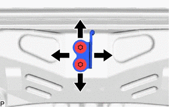
9. ADJUST LUGGAGE COMPARTMENT DOOR
| (a) Loosen the 4 door side hinge bolts to adjust the door horizontally and vertically. |
|
(b) Tighten the 4 bolts after adjustment.
Torque:
7.5 N·m {76 kgf·cm, 66 in·lbf}
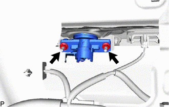
| (c) Using a T40 "TORX" socket wrench, slightly loosen the 2 striker mounting screws. |
|
(d) Using a brass bar and a hammer, hit the striker to adjust its position.
(e) Using a T40 "TORX" socket wrench, tighten the 2 striker mounting screws after adjustment.
Torque:
23 N·m {235 kgf·cm, 17 ft·lbf}
10. INSTALL BACK DOOR UPPER HINGE PROTECTOR LH
Click here
11. INSTALL BACK DOOR UPPER HINGE PROTECTOR RH
Click here
12. INSTALL LUGGAGE COMPARTMENT DOOR COVER
Click here
13. INSTALL REAR FLOOR FINISH PLATE
Click here
14. INSTALL NO. 1 LUGGAGE COMPARTMENT TRIM HOOK
Click here
15. INSTALL BAGGAGE HOLDER NET
Click here
16. INSTALL SPARE WHEEL COVER ASSEMBLY
Click here
Components
COMPONENTS
ILLUSTRATION
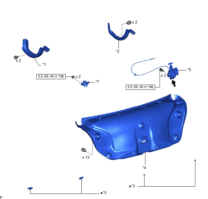
|
*1 | BACK DOOR UPPER HINGE PROTECTOR LH |
*2 | BACK DOOR UPPER HINGE PROTECTOR RH |
|
*3 | HOLE PLUG |
*4 | LUGGAGE COMPARTMENT DOOR COVER |
|
*5 | LUGGAGE COMPARTMENT DOOR CUSHION |
*6 | LUGGAGE COMPARTMENT DOOR LOCK ASSEMBLY |
|
*7 | LUGGAGE COMPARTMENT DOOR LOCK CYLINDER ASSEMBLY |
- | - |
 |
N*m (kgf*cm, ft.*lbf): Specified torque |
â—Ź | Non-reusable part |
 |
MP grease | - |
- |
ILLUSTRATION
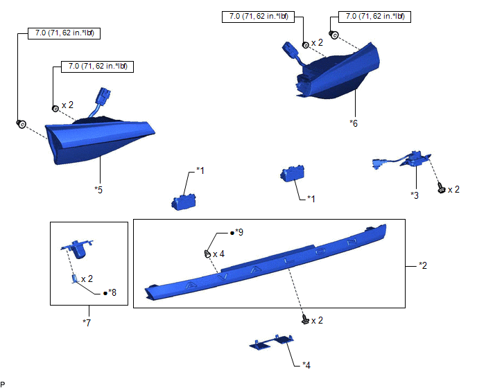
|
*1 | LICENSE PLATE LIGHT ASSEMBLY |
*2 | LUGGAGE COMPARTMENT DOOR OUTSIDE GARNISH SUB-ASSEMBLY |
|
*3 | LUGGAGE ELECTRICAL KEY SWITCH |
*4 | NO. 2 BACK DOOR OUTSIDE GARNISH |
|
*5 | REAR LIGHT ASSEMBLY LH |
*6 | REAR LIGHT ASSEMBLY RH |
|
*7 | TELEVISION CAMERA ASSEMBLY |
*8 | GROMMET |
|
*9 | CLIP |
- | - |
|
|
N*m (kgf*cm, ft.*lbf): Specified torque |
â—Ź | Non-reusable part |
ILLUSTRATION
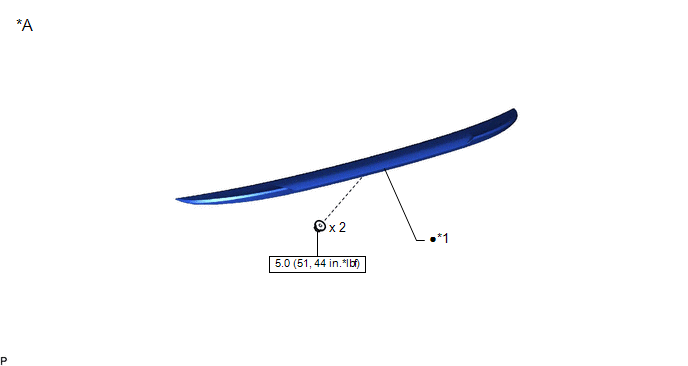
|
*A | w/ Rear Spoiler |
- | - |
|
*1 | REAR SPOILER SUB-ASSEMBLY |
- | - |
|
|
N*m (kgf*cm, ft.*lbf): Specified torque |
â—Ź | Non-reusable part |
Disassembly
DISASSEMBLY
CAUTION / NOTICE / HINT
The
necessary procedures (adjustment, calibration, initialization, or
registration) that must be performed after parts are removed and
installed, or replaced during luggage compartment door
rmoval/installation are shown below.
Necessary Procedure After Parts Removed/Installed/Replaced (for Gasoline Model) |
Replaced Part or Performed Procedure |
Necessary Procedure | Effect/Inoperative Function When Necessary Procedures are not Performed |
Link |
| Television camera assembly (w/ Parking assist monitor system) |
- Parking assist monitor system initialization
- Television camera assembly optical axis (Back camera position setting)
| Parking assist monitor system |
 |
|
Television camera assembly (w/ Panoramic view monitor system) |
- Rear television camera view adjustment
- Television camera assembly optical axis adjustment (Back camera position setting)
| Panoramic view monitor system |
|
Necessary Procedure After Parts Removed/Installed/Replaced (for HV Model) |
Replaced Part or Performed Procedure |
Necessary Procedure | Effect/Inoperative Function When Necessary Procedures are not Performed |
Link |
| Television camera assembly (w/ Parking assist monitor system) |
- Parking assist monitor system initialization
- Television camera assembly optical axis (Back camera position setting)
| Parking assist monitor system |
|
|
Television camera assembly (w/ Panoramic view monitor system) |
- Rear television camera view adjustment
- Television camera assembly optical axis adjustment (Back camera position setting)
| Panoramic view monitor system |
|
PROCEDURE
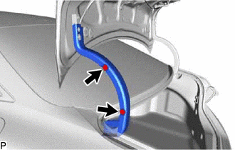
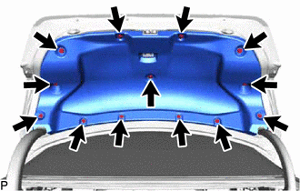
1. REMOVE LUGGAGE COMPARTMENT DOOR COVER
| (a) Using a clip remover, remove the 13 clips and luggage compartment door cover. |
|
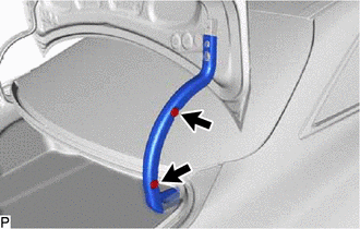
2. REMOVE BACK DOOR UPPER HINGE PROTECTOR LH
| (a) Remove the 2 clips and back door upper hinge protector LH. |
|
3. REMOVE BACK DOOR UPPER HINGE PROTECTOR RH
| (a) Remove the 2 clips and back door upper hinge protector RH. |
|
4. REMOVE LUGGAGE COMPARTMENT DOOR LOCK ASSEMBLY
Click here
5. REMOVE LUGGAGE COMPARTMENT DOOR LOCK CYLINDER ASSEMBLY
| (a) Remove the 2 nuts and luggage compartment door lock cylinder assembly. |
|
6. REMOVE LUGGAGE COMPARTMENT DOOR CUSHION
| (a) Disengage the 8 claws to remove the 2 luggage compartment door cushions. |
|
7. REMOVE HOLE PLUG
| (a) Remove the 2 hole plugs. |
|
8. REMOVE REAR LIGHT ASSEMBLY LH
Click here
9. REMOVE REAR LIGHT ASSEMBLY RH
HINT:
Use the same procedure as for the LH side.
10. REMOVE NO. 2 BACK DOOR OUTSIDE GARNISH
Click here
11. REMOVE LUGGAGE COMPARTMENT DOOR OUTSIDE GARNISH SUB-ASSEMBLY
Click here
12. REMOVE LUGGAGE ELECTRICAL KEY SWITCH
Click here
13. REMOVE TELEVISION CAMERA ASSEMBLY
Click here
14. REMOVE LICENSE PLATE LIGHT ASSEMBLY
Click here
HINT:
Use the same procedure as for the LH side.
15. REMOVE REAR SPOILER SUB-ASSEMBLY (w/ Rear Spoiler)
Click here
Reassembly
REASSEMBLY
PROCEDURE
1. INSTALL REAR SPOILER SUB-ASSEMBLY (w/ Rear Spoiler)
Click here 
2. INSTALL LICENSE PLATE LIGHT ASSEMBLY
Click here
HINT:
Use the same procedure as for the LH side.
3. INSTALL TELEVISION CAMERA ASSEMBLY
Click here
4. INSTALL LUGGAGE ELECTRICAL KEY SWITCH
Click here
5. INSTALL LUGGAGE COMPARTMENT DOOR OUTSIDE GARNISH SUB-ASSEMBLY
Click here
6. INSTALL NO. 2 BACK DOOR OUTSIDE GARNISH
Click here
7. INSTALL REAR LIGHT ASSEMBLY LH
Click here
8. INSTALL REAR LIGHT ASSEMBLY RH
HINT:
Use the same procedure as for the LH side.
9. INSTALL HOLE PLUG
| (a) Install 2 new hole plugs. | |
10. INSTALL LUGGAGE COMPARTMENT DOOR CUSHION
| (a) Engage the 8 claws to install 2 new luggage compartment door cushions. |
|
11. INSTALL LUGGAGE COMPARTMENT DOOR LOCK CYLINDER ASSEMBLY
| (a) Install the luggage compartment door lock cylinder assembly with the 2 nuts.
Torque: 5.5 N·m {56 kgf·cm, 49 in·lbf} | |
12. INSTALL LUGGAGE COMPARTMENT DOOR LOCK ASSEMBLY
Click here
13. INSTALL BACK DOOR UPPER HINGE PROTECTOR LH
| (a) Install the back door upper hinge protector LH with the 2 clips. |
|
14. INSTALL BACK DOOR UPPER HINGE PROTECTOR RH
| (a) Install the back door upper hinge protector RH with the 2 clips. |
|
15. INSTALL LUGGAGE COMPARTMENT DOOR COVER
| (a) Install the luggage compartment door cover with the 13 clips. |
|