Components
COMPONENTS
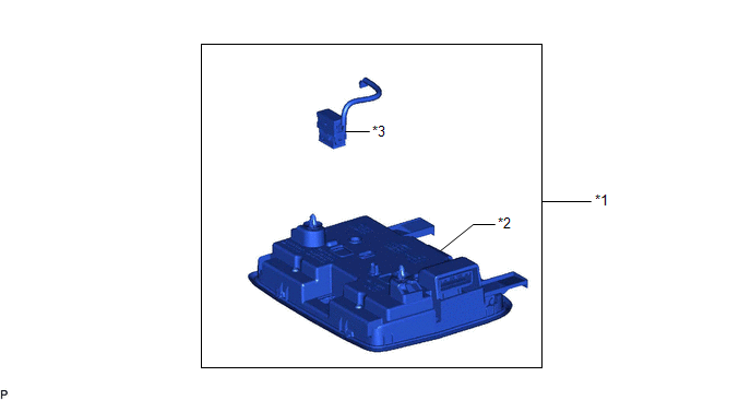
ILLUSTRATION
|
*1 | ROOF CONSOLE BOX ASSEMBLY |
*2 | ROOF CONSOLE BOX SUB-ASSEMBLY |
|
*3 | TELEPHONE MICROPHONE ASSEMBLY |
- | - |
Inspection
INSPECTION
PROCEDURE
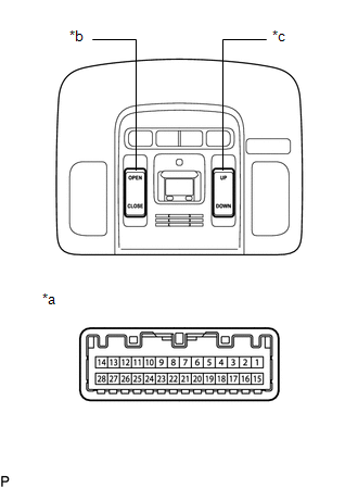
1. INSPECT SLIDING ROOF SWITCH (ROOF CONSOLE BOX SUB-ASSEMBLY)
| (a) Measure the resistance according to the value(s) in the table below. Standard Resistance:
If the result is not as specified, replace the sliding roof switch (roof console box sub-assembly). |
|
Installation
INSTALLATION
PROCEDURE
1. INSTALL ROOF CONSOLE BOX SUB-ASSEMBLY
2. INSTALL TELEPHONE MICROPHONE ASSEMBLY
Click here 
3. INSTALL ROOF CONSOLE BOX ASSEMBLY
Click here
Removal
REMOVAL
PROCEDURE
1. REMOVE ROOF CONSOLE BOX ASSEMBLY
Click here

2. REMOVE TELEPHONE MICROPHONE ASSEMBLY
Click here
3. REMOVE ROOF CONSOLE BOX SUB-ASSEMBLY
Toyota Avalon (XX50) 2019-2022 Service & Repair Manual > Garage Door Opener: Garage Door Opener System(for Gasoline Model)
On-vehicle Inspection ON-VEHICLE INSPECTION PROCEDURE 1. INSPECT GARAGE DOOR OPENER (a) Press each garage door opener ("HomeLink") switch and check that the ("HomeLink") indicator light turns on. If one or more of the garage door opener ("HomeLink") switches does not turn on the ("HomeLink") indicat ...