Components
COMPONENTS
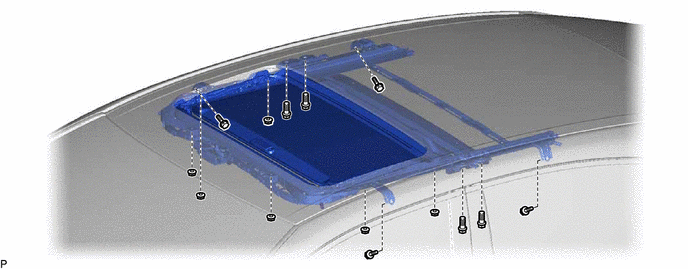
ILLUSTRATION
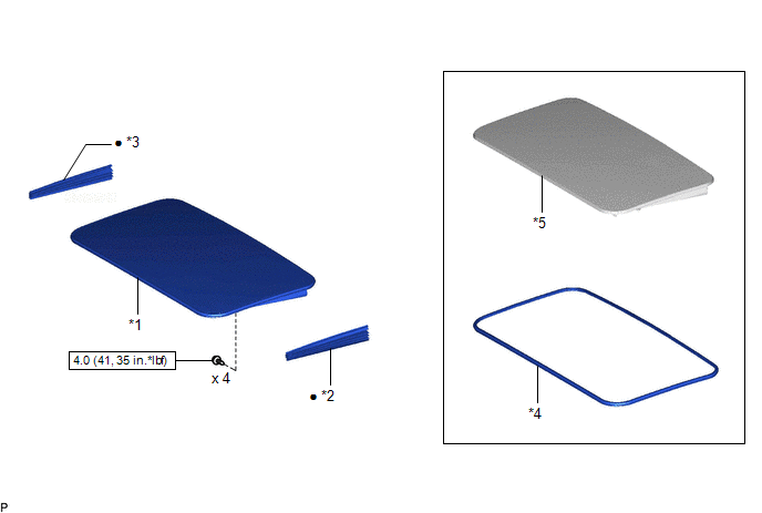
|
*1 | SLIDING ROOF GLASS SUB-ASSEMBLY |
*2 | SLIDING ROOF SIDE GARNISH LH |
|
*3 | SLIDING ROOF SIDE GARNISH RH |
*4 | SLIDING ROOF WEATHERSTRIP |
|
*5 | SLIDING ROOF PANEL SUB-ASSEMBLY |
- | - |
 |
N*m (kgf*cm, ft.*lbf): Specified torque |
â—Ź | Non-reusable part |
ILLUSTRATION
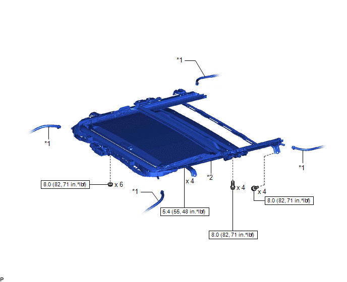
|
*1 | SLIDING ROOF DRAIN HOSE |
*2 | SLIDING ROOF HOUSING ASSEMBLY |
 |
N*m (kgf*cm, ft.*lbf): Specified torque |
- | - |
ILLUSTRATION
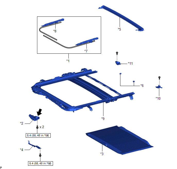
|
*1 | SLIDING ROOF DRIVE CABLE SUB-ASSEMBLY |
*2 | SLIDING ROOF DRIVE GEAR ASSEMBLY |
|
*3 | SUNSHADE TRIM SUB-ASSEMBLY |
*4 | MAP LIGHT BRACKET |
|
*5 | REAR ROOF DRIP CHANNEL |
*6 | REAR SLIDING ROOF SUNSHADE STOPPER |
|
*7 | SLIDING ROOF DRIVE CABLE LH |
*8 | SLIDING ROOF DRIVE CABLE RH |
|
*9 | SLIDING ROOF HOUSING SUB-ASSEMBLY |
*10 | SLIDING ROOF PIECE SUB-ASSEMBLY LH |
|
*11 | SLIDING ROOF PIECE SUB-ASSEMBLY RH |
- | - |
 |
N*m (kgf*cm, ft.*lbf): Specified torque |
 |
MP grease |
Disassembly
DISASSEMBLY
PROCEDURE
1. REMOVE SLIDING ROOF DRIVE GEAR ASSEMBLY
(a) Remove the bolt.
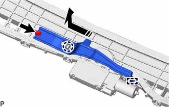
 |
Remove in this Direction |
(b) Disengage the claw and guide as shown in the illustration to remove the map light bracket.
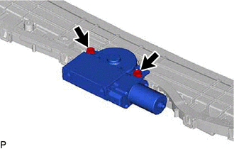
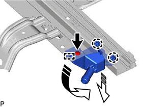
| (c) Remove the 2 bolts and sliding roof drive gear assembly. |
|
2. REMOVE SUNSHADE TRIM SUB-ASSEMBLY
(a) Remove the screw.
 | Remove in this Direction (1) |
 |
Remove in this Direction (2) |
HINT:
Use the same procedure for the RH side.
(b)
Move the sliding roof piece sub-assembly LH in the direction indicated
by the arrow (1) shown in the illustration to disengage the guide.
HINT:
Use the same procedure for the RH side.
(c)
Move the sliding roof piece sub-assembly LH in the direction indicated
by the arrow (2) shown in the illustration to disengage the 2 claws and
remove it.
HINT:
Use the same procedure for the RH side.
(d) Remove the rear sliding roof sunshade stopper as shown in the illustration.
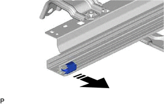
 | Remove in this Direction |
HINT:
Use the same procedure for the RH side.
(e) Slide and remove the sunshade trim sub-assembly as shown in the illustration.
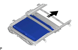
 | Remove in this Direction |
3. REMOVE SLIDING ROOF DRIVE CABLE SUB-ASSEMBLY
NOTICE:
Do not disassemble the sliding roof drive cable sub-assembly except when replacing it.
(a) Using a screwdriver, disengage the 2 claws as shown in the illustration.
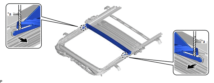
|
*a | Protective Tape |
- | - |
 |
Remove in this Direction |
- | - |
HINT:
Tape the screwdriver tip before use.
(b) Slide and remove the rear roof drip channel as shown in the illustration.
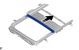
 | Remove in this Direction |
(c) Hold down the roof wind deflector panel sub-assembly.
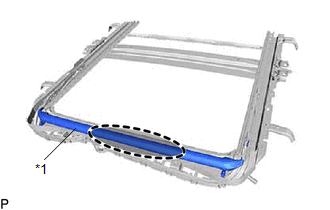
|
*1 | Roof Wind Deflector Panel Sub-assembly |
 |
Hold Position |
(d) Using a screwdriver, slide the sliding roof drive cable LH as shown in the illustration to remove it.
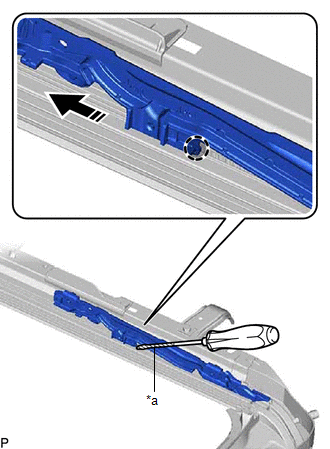
|
*a | Protective Tape |
 |
Push Position |
 |
Remove in this Direction |
HINT:
- Tape the screwdriver tip before use.
- Use the same procedure for the RH side.
Installation
INSTALLATION
PROCEDURE
1. INSTALL SLIDING ROOF HOUSING ASSEMBLY
(a) Loosen the 4 bolts of the brackets of the sliding roof housing assembly.
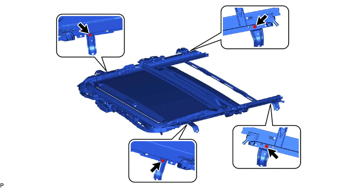
(b) Temporarily install the sliding roof housing assembly with the 6 nuts and 8 bolts.
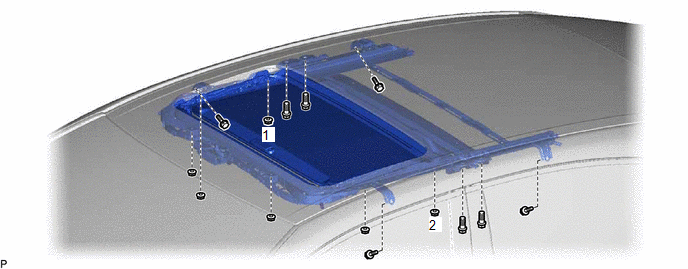
(c) Tighten the 2 nuts.
HINT:
Tighten the 2 nuts in the order shown in the illustration.
Torque:
8.0 N·m {82 kgf·cm, 71 in·lbf}
(d) Tighten the 4 nuts.
Torque:
8.0 N·m {82 kgf·cm, 71 in·lbf}
(e) Tighten the 12 bolts to install the sliding roof housing assembly.
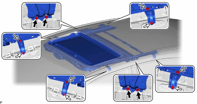
 | Bolt (A) |
 | Bolt (B) |
 |
Bolt (C) | - |
- |
HINT:
- The brackets can be installed in any order.
- Tighten the bolts in the order of (A), (B) and then (C).
Torque:
Bolt (A), (B) :
8.0 N·m {82 kgf·cm, 71 in·lbf}
Bolt (C) :
5.4 N·m {55 kgf·cm, 48 in·lbf}
2. CONNECT SLIDING ROOF DRAIN HOSE
HINT:
Use the same procedure for all of the sliding roof drain hoses.
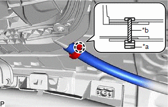
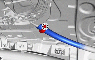
(a) for Clamp Type:
| (1) Connect the sliding roof drain hose.
HINT: Slide the hose to the base of the drain pipe. | |
(2) Engage the claw to secure the sliding roof drain hose.
HINT:
Make sure that the clamp is on the marking.
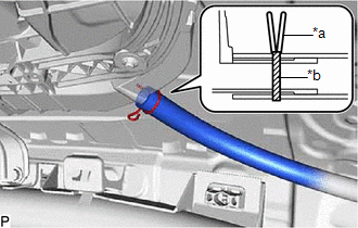
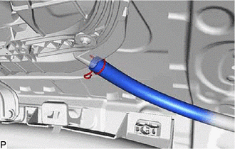
(b) for Clip Type:
| (1) Expand the clip to connect the sliding roof drain hose. HINT:
Slide the hose to the base of the drain pipe. | |
(2) Release the clip to secure the sliding roof drain hose.
HINT:
Make sure that the clip is on the marking.
3. INSTALL SLIDING ROOF WEATHERSTRIP
(a) Install the sliding roof weatherstrip.
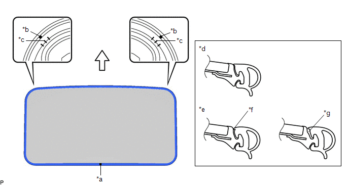
|
*a | Joint |
*b | Alignment Mark (Blue) |
|
*c | Middle Mark |
*d | Correct |
|
*e | Incorrect |
*f | Pinched |
|
*g | Gap (raised, wavy, etc.) |
- | - |
 |
Front Side | - |
- |
(1) Position the joint of the sliding roof weatherstrip on the rear side.
(2)
Align the alignment marks (Blue) on the sliding roof weatherstrip with
the middle marks on the front corners of the sliding roof panel
sub-assembly and install the sliding roof weatherstrip.
HINT:
Make sure to install the lip of the sliding roof weatherstrip securely.
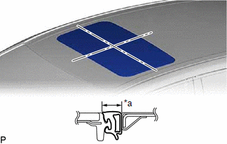
4. INSTALL SLIDING ROOF GLASS SUB-ASSEMBLY
(a) Using a T25 "TORX" socket wrench, temporarily install the sliding roof glass sub-assembly with the 4 screws.
(b) Perform a level check.
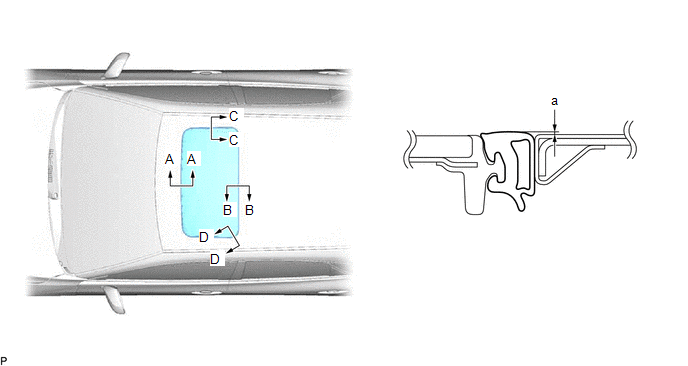
(1)
Check the difference in level "a" between the roof panel and the upper
surface of the sliding roof weatherstrip when the sliding roof glass
sub-assembly is fully closed.
HINT:
"+"
represents the condition that the glass is above the panel level. "-"
represents the condition that the glass is below the panel level.
Standard:
|
Area | Measurement |
Area | Measurement |
|
A - A | -2.0 to 1.0 mm (-0.0787 to 0.0394 in.) |
B - B | -1.0 to 2.0 mm (-0.0394 to 0.0787 in.) |
|
C - C | -1.5 to 1.5 mm (-0.0591 to 0.0591 in.) |
D - D | -1.0 to 1.5 mm (-0.0394 to 0.0591 in.) |
| (c) Perform a gap check. (1) Check the gap between the roof panel and sliding roof glass sub-assembly.
NOTICE: The gap must be even all around. | |
(d)
After adjusting the sliding roof glass sub-assembly, using a T25 "TORX"
socket wrench, install the sliding roof glass sub-assembly with the 4
screws.
Torque:
4.0 N·m {41 kgf·cm, 35 in·lbf}
5. CHECK FOR WATER LEAK
(a) After adjusting the sliding roof glass sub-assembly, check for water leakage into the vehicle interior.
(b) If there are any leaks, readjust the sliding roof glass sub-assembly.
6. INSTALL CURTAIN SHIELD AIRBAG ASSEMBLY LH
Click here

7. INSTALL CURTAIN SHIELD AIRBAG ASSEMBLY RH
HINT:
Use the same procedure as for the LH side.
8. INSTALL SLIDING ROOF SIDE GARNISH LH
(a) Engage the 4 claws to install a new sliding roof side garnish LH.
9. INSTALL SLIDING ROOF SIDE GARNISH RH
HINT:
Use the same procedure as for the LH side.
10. INITIALIZE SLIDING ROOF SYSTEM
for Gasoline Model: Click here 
for HV Model: Click here

11. CHECK SLIDING ROOF SYSTEM
for Gasoline Model: Click here

for HV Model: Click here

Reassembly
REASSEMBLY
PROCEDURE
1. INSTALL SLIDING ROOF DRIVE CABLE SUB-ASSEMBLY
(a) Hold down the roof wind deflector panel sub-assembly.
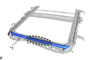
|
*1 | Roof Wind Deflector Panel Sub-assembly |
 |
Hold Position |
(b) Using a screwdriver, slide the sliding roof drive cable LH as shown in the illustration to install it.
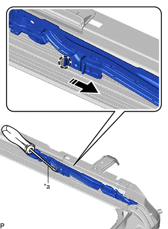
|
*a | Protective Tape |
 |
Push Position |
 |
Install in this Direction |
HINT:
- Tape the screwdriver tip before use.
- Use the same procedure for the RH side.
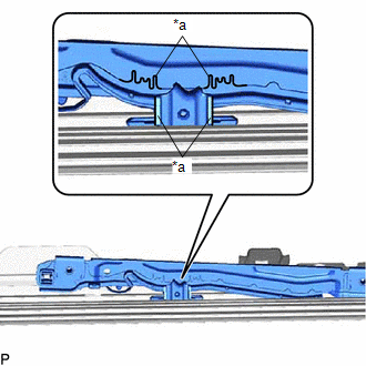
(c) Adjust Fully Closed Position:
| (1)
Using a screwdriver, slide the sliding roof drive cable LH in either
direction and align the alignment marks as shown in the illustration. HINT:
Use the same procedure for the RH side. | |
(d) Insert the rear roof drip channel into the sliding roof housing sub-assembly as shown in the illustration.
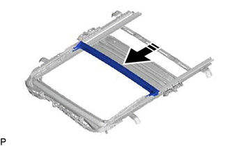
 | Install in this Direction |
(e) Engage the 2 claws as shown in the illustration to install the rear roof drip channel.
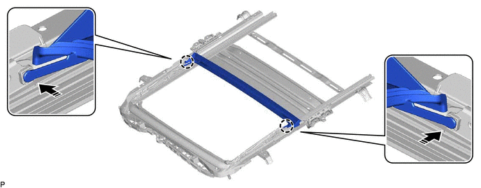
 | Install in this Direction |
- | - |
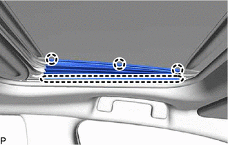
2. INSTALL SUNSHADE TRIM SUB-ASSEMBLY
(a) Insert the sunshade trim sub-assembly into the sliding roof housing sub-assembly as shown in the illustration to install it.
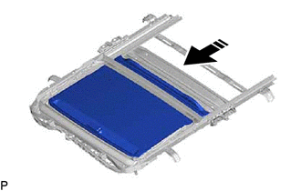
 | Install in this Direction |
(b) Install the rear sliding roof sunshade stopper as shown in the illustration.
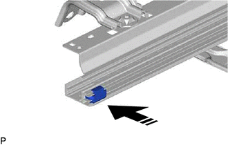
 | Install in this Direction |
HINT:
Use the same procedure for the RH side.
(c)
Move the sliding roof piece sub-assembly LH in the direction indicated
by the arrow (1) shown in the illustration to engage the 2 claws.
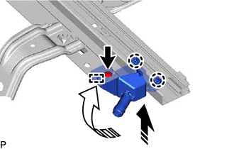
 | Install in this Direction (1) |
 |
Install in this Direction (2) |
HINT:
Use the same procedure for the RH side.
(d)
Move the sliding roof piece sub-assembly LH in the direction indicated
by the arrow (2) shown in the illustration to engage the guide.
HINT:
Use the same procedure for the RH side.
(e) Install the sliding roof piece sub-assembly LH with the screw.
HINT:
Use the same procedure for the RH side.
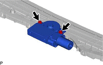
3. INSTALL SLIDING ROOF DRIVE GEAR ASSEMBLY
(a) Apply MP grease to the gear of the sliding roof drive gear assembly.
| (b) Install the sliding roof drive gear assembly with the 2 bolts.
Torque: 5.4 N·m {55 kgf·cm, 48 in·lbf} | |
(c) Engage the guide and claw as shown in the illustration.
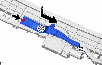
 | Install in this Direction |
(d) Install the map light bracket with the bolt.
Torque:
5.4 N·m {55 kgf·cm, 48 in·lbf}
Removal
REMOVAL
CAUTION / NOTICE / HINT
The
necessary procedures (adjustment, calibration, initialization or
registration) that must be performed after parts are removed and
installed, or replaced during sliding roof housing removal/installation
are shown below.
Necessary Procedure After Parts Removed/Installed/Replaced (for Gasoline Model) |
Replaced Part or Performed Procedure |
Necessary Procedure | Effect/Inoperative Function when Necessary Procedure not Performed |
Link |
|
*: When performing learning using the Techstream.
Click here  |
|
Disconnect cable from negative (-) battery terminal |
Perform steering sensor zero point calibration |
Lane Departure Alert System (w/ Steering Control) |
 |
|
Pre-collision System |
|
Intelligent Clearance Sonar System* |
|
Lighting System (for Gasoline Model with Cornering Light) |
|
Memorize steering angle neutral point |
Parking Assist Monitor System |
 |
|
Panoramic View Monitor System |
|
Front passenger seat | Zero point calibration (Occupant classification system) |
- Occupant classification system
- Passenger airbag ON/OFF indicator
- Airbag system (Front passenger side)
- Seat belt warning system (Front passenger)
|
 |
- Sliding roof ECU (sliding roof drive gear sub-assembly)
- Sliding roof glass sub-assembly
- Sliding roof drive cable sub-assembly
- Sliding roof drive gear sub-assembly
| Initialize sliding roof system |
- Auto operation function
- Jam protection function
- Key-off operation function
- Key-linked function
- Wireless transmitter-linked function
- Sliding roof open warning function
|
 |
Necessary Procedure After Parts Removed/Installed/Replaced (for HV Model) |
Replaced Part or Performed Procedure |
Necessary Procedure | Effect/Inoperative Function when Necessary Procedure not Performed |
Link |
|
*: When performing learning using the Techstream.
Click here  |
|
Disconnect cable from negative (-) auxiliary battery terminal |
Perform steering sensor zero point calibration |
Lane Departure Alert System (w/ Steering Control) |
 |
|
Pre-collision System |
|
Intelligent Clearance Sonar System* |
|
Lighting System (for HV Model with Cornering Light) |
|
Memorize steering angle neutral point |
Parking Assist Monitor System |
 |
|
Panoramic View Monitor System |
|
Front passenger seat | Zero point calibration (Occupant classification system) |
- Occupant classification system
- Passenger airbag ON/OFF indicator
- Airbag system (Front passenger side)
- Seat belt warning system (Front passenger)
|
 |
- Sliding roof ECU (sliding roof drive gear sub-assembly)
- Sliding roof glass sub-assembly
- Sliding roof drive cable sub-assembly
- Sliding roof drive gear sub-assembly
| Initialize sliding roof system |
- Auto operation function
- Jam protection function
- Key-off operation function
- Key-linked function
- Wireless transmitter-linked function
- Sliding roof open warning function
|
 |
CAUTION:
Some
of these service operations affect the SRS airbag system. Read the
precautionary notices concerning the SRS airbag system before servicing.
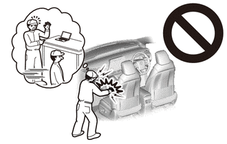
for Gasoline Model: Click here

for HV Model: Click here

PROCEDURE
1. REMOVE SLIDING ROOF SIDE GARNISH LH
| (a) Disengage the 4 claws to remove the sliding roof side garnish LH. |
|
2. REMOVE SLIDING ROOF SIDE GARNISH RH
HINT:
Use the same procedure as for the LH side.
3. REMOVE SLIDING ROOF GLASS SUB-ASSEMBLY
(a) Move the sliding roof glass sub-assembly to the fully closed position.
(b) Using a T25 "TORX" socket wrench, remove the 4 screws and sliding roof glass sub-assembly.
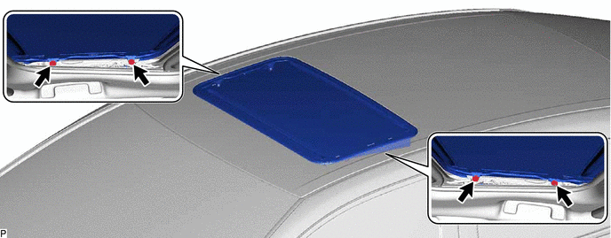
NOTICE:
To
prevent the sliding roof glass sub-assembly and sliding roof drive gear
assembly from becoming misaligned, move the sliding roof glass
sub-assembly (sliding roof drive cable sub-assembly) to the fully closed
position before removing it.
4. REMOVE SLIDING ROOF WEATHERSTRIP
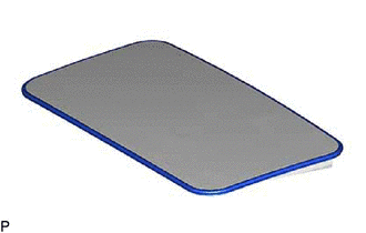
| (a) Remove the sliding roof weatherstrip from the sliding roof panel sub-assembly. |
|
5. REMOVE CURTAIN SHIELD AIRBAG ASSEMBLY LH
Click here

6. REMOVE CURTAIN SHIELD AIRBAG ASSEMBLY RH
HINT:
Use the same procedure as for the LH side.
7. DISCONNECT SLIDING ROOF DRAIN HOSE
HINT:
Use the same procedure for all of the sliding roof drain hoses.
(a) for Clamp Type:
| (1) Disengage the claw and disconnect the sliding roof drain hose. |
|
(b) for Clip Type:
| (1) Expand the clip and disconnect the sliding roof drain hose. |
|
8. REMOVE SLIDING ROOF HOUSING ASSEMBLY
(a) Remove the 8 bolts, 6 nuts and sliding roof housing assembly.
