On-vehicle Inspection
ON-VEHICLE INSPECTION
PROCEDURE
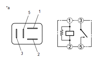
1. INSPECT H-LP LH RELAY
|
*a | Component without harness connected (H-LP LH Relay) |
(a) Measure the resistance according to the value(s) in the table below.
Standard Resistance:
|
Tester Connection | Condition |
Specified Condition |
|---|---|---|
|
3 - 5 | Voltage not applied between terminals 1 and 2 |
10 kΩ or higher |
|
3 - 5 | Voltage applied between terminals 1 and 2 |
Below 1 Ω |
If the result is not as specified, replace the H-LP LH relay.
2. INSPECT H-LP RH RELAY
|
*a | Component without harness connected (H-LP RH Relay) |
(a) Measure the resistance according to the value(s) in the table below.
Standard Resistance:
|
Tester Connection | Condition |
Specified Condition |
|---|---|---|
|
3 - 5 | Voltage not applied between terminals 1 and 2 |
10 kΩ or higher |
|
3 - 5 | Voltage applied between terminals 1 and 2 |
Below 1 Ω |
If the result is not as specified, replace the H-LP RH relay.
3. INSPECT DIM RELAY (w/o Cornering Light)
|
*a | Component without harness connected (DIM Relay) |
(a) Measure the resistance according to the value(s) in the table below.
Standard Resistance:
|
Tester Connection | Condition |
Specified Condition |
|---|---|---|
|
3 - 5 | Voltage not applied between terminals 1 and 2 |
10 kΩ or higher |
|
3 - 5 | Voltage applied between terminals 1 and 2 |
Below 1 Ω |
If the result is not as specified, replace the DIM relay.
4. INSPECT DRL RELAY (w/o Cornering Light)
|
*a | Component without harness connected (DRL Relay) |
(a) Measure the resistance according to the value(s) in the table below.
Standard Resistance:
|
Tester Connection | Condition |
Specified Condition |
|---|---|---|
|
3 - 5 | Voltage not applied between terminals 1 and 2 |
10 kΩ or higher |
|
3 - 5 | Voltage applied between terminals 1 and 2 |
Below 1 Ω |
If the result is not as specified, replace the DRL relay.
Toyota Avalon (XX50) 2019-2022 Service & Repair Manual > Ua80e Automatic Transmission / Transaxle: Differential Case
Components COMPONENTS ILLUSTRATION *1 FRONT DIFFERENTIAL CASE FRONT TAPERED ROLLER BEARING (INNER RACE) *2 FRONT DIFFERENTIAL CASE FRONT TAPERED ROLLER BEARING (OUTER RACE) *3 FRONT DIFFERENTIAL CASE REAR TAPERED ROLLER BEARING (INNER RACE) *4 FRONT DIFFERENTIAL CASE REAR TAPERED ROLLER BEARING (OUT ...


