Components
COMPONENTS
ILLUSTRATION
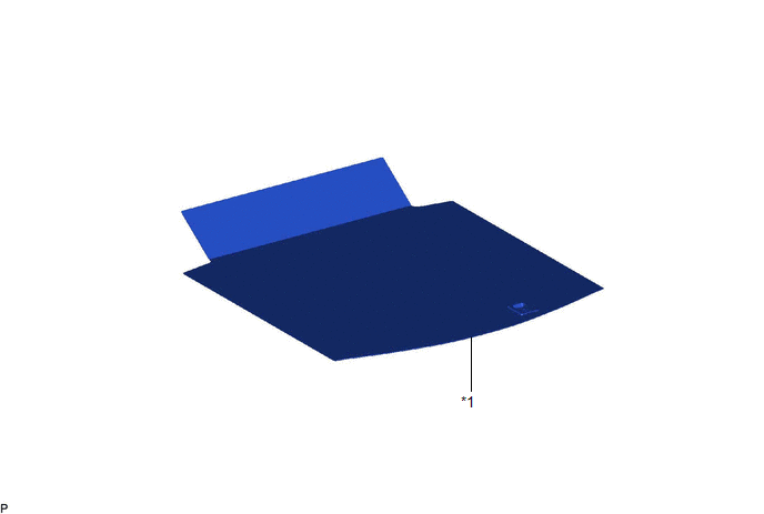
|
*1 | SPARE WHEEL COVER ASSEMBLY |
- | - |
ILLUSTRATION
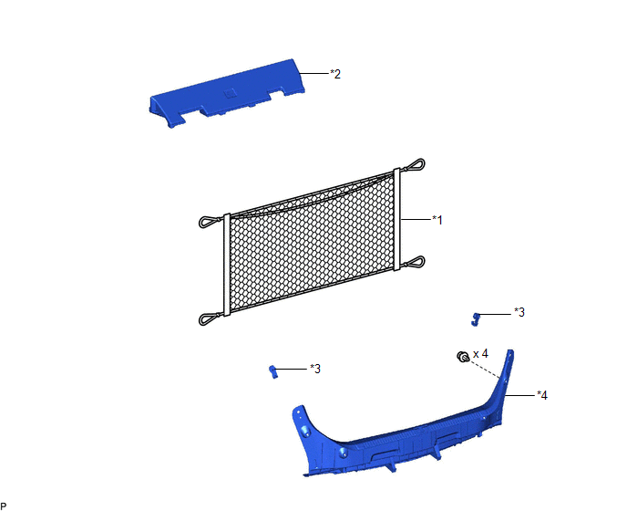
|
*1 | BAGGAGE HOLDER NET |
*2 | LUGGAGE COMPARTMENT INNER TRIM PAD |
|
*3 | NO. 1 LUGGAGE COMPARTMENT TRIM HOOK |
*4 | REAR FLOOR FINISH PLATE |
ILLUSTRATION
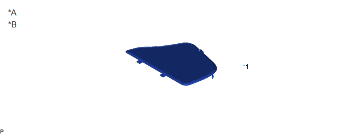
|
*A | for HV Model |
*B | for RH Side |
|
*1 | LUGGAGE TRIM SERVICE HOLE COVER |
- | - |
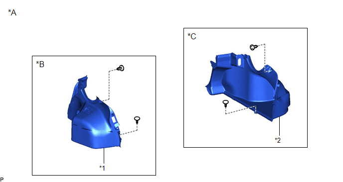
ILLUSTRATION
|
*A | for Gasoline Model |
*B | for LH Side |
|
*C | for RH Side |
- | - |
|
*1 | LUGGAGE COMPARTMENT TRIM INNER COVER LH |
*2 | LUGGAGE COMPARTMENT TRIM INNER COVER RH |
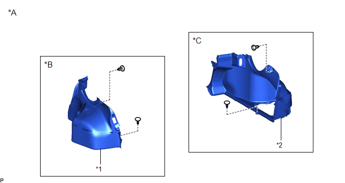
ILLUSTRATION
|
*A | for HV Model |
*B | for LH Side |
|
*C | for RH Side |
- | - |
|
*1 | LUGGAGE COMPARTMENT TRIM INNER COVER LH |
*2 | LUGGAGE COMPARTMENT TRIM INNER COVER RH |
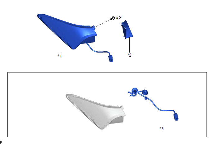
ILLUSTRATION
|
*1 | REAR COMBINATION LIGHT ASSEMBLY |
*2 | REAR COMBINATION LIGHT COVER |
|
*3 | REAR COMBINATION LIGHT SOCKET AND WIRE |
- | - |
Disassembly
DISASSEMBLY
CAUTION / NOTICE / HINT
HINT:
- Use the same procedure for the RH side and LH side.
- The following procedure is for the LH side.
PROCEDURE
1. REMOVE REAR COMBINATION LIGHT SOCKET AND WIRE
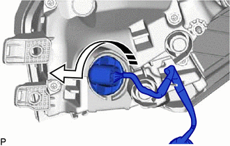
(a) Turn the rear combination light socket and wire as shown in the illustration to separate it.
 |
Separate in this Direction |
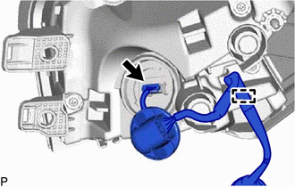
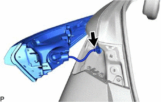
| (b) Disconnect the connector. | |
(c) Disengage the clamp to remove the rear combination light socket and wire.
Inspection
INSPECTION
PROCEDURE
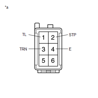
1. INSPECT REAR COMBINATION LIGHT ASSEMBLY LH (w/o Sequential Turn Light)
|
*a | Component without harness connected
(Rear Combination Light Assembly LH) |
(a) Apply auxiliary battery voltage to the rear combination light assembly LH and check that the lights illuminate.
OK:
|
Measurement Condition | Specified Condition |
|
Auxiliary battery positive (+) → Terminal 1 (TL) Auxiliary battery negative (-) → Terminal 4 (E) |
Taillight and side marker light illuminate |
|
Auxiliary battery positive (+) → Terminal 2 (STP) Auxiliary battery negative (-) → Terminal 4 (E) |
Stop light illuminates |
|
Auxiliary battery positive (+) → Terminal 3 (TRN) Auxiliary battery negative (-) → Terminal 4 (E) |
Turn signal light illuminates |
If the result is not as specified, replace the rear combination light assembly LH.
2. INSPECT REAR COMBINATION LIGHT ASSEMBLY RH (w/o Sequential Turn Light)

|
*a | Component without harness connected
(Rear Combination Light Assembly RH) |
(a) Apply auxiliary battery voltage to the rear combination light assembly RH and check that the lights illuminate.
OK:
|
Measurement Condition | Specified Condition |
|
Auxiliary battery positive (+) → Terminal 1 (TL) Auxiliary battery negative (-) → Terminal 4 (E) |
Taillight and side marker light illuminate |
|
Auxiliary battery positive (+) → Terminal 2 (STP) Auxiliary battery negative (-) → Terminal 4 (E) |
Stop light illuminates |
|
Auxiliary battery positive (+) → Terminal 3 (TRN) Auxiliary battery negative (-) → Terminal 4 (E) |
Turn signal light illuminates |
If the result is not as specified, replace the rear combination light assembly RH.
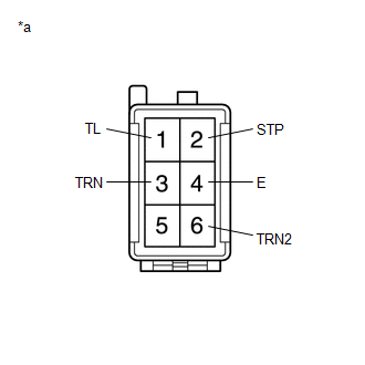
3. INSPECT REAR COMBINATION LIGHT ASSEMBLY LH (w/ Sequential Turn Light)
|
*a | Component without harness connected
(Rear Combination Light Assembly LH) |
(a) Apply auxiliary battery voltage to the rear combination light assembly LH and check that the lights illuminate.
OK:
|
Measurement Condition | Specified Condition |
|
Auxiliary battery positive (+) → Terminal 1 (TL) Auxiliary battery negative (-) → Terminal 4 (E) |
Taillight and side marker light illuminates |
|
Auxiliary battery positive (+) → Terminal 2 (STP) Auxiliary battery negative (-) → Terminal 4 (E) |
Stop light illuminates |
|
Auxiliary battery positive (+) → Terminal 3 (TRN) Auxiliary battery positive (+) → Terminal 6 (TRN2)
Auxiliary battery negative (-) → Terminal 4 (E) |
Turn signal lights illuminate |
If the result is not as specified, replace the rear combination light assembly LH.
4. INSPECT REAR COMBINATION LIGHT ASSEMBLY RH (w/ Sequential Turn Light)

|
*a | Component without harness connected
(Rear Combination Light Assembly RH) |
(a) Apply auxiliary battery voltage to the rear combination light assembly RH and check that the lights illuminate.
OK:
|
Measurement Condition | Specified Condition |
|
Auxiliary battery positive (+) → Terminal 1 (TL) Auxiliary battery negative (-) → Terminal 4 (E) |
Taillight and side marker light illuminates |
|
Auxiliary battery positive (+) → Terminal 2 (STP) Auxiliary battery negative (-) → Terminal 4 (E) |
Stop light illuminates |
|
Auxiliary battery positive (+) → Terminal 3 (TRN) Auxiliary battery positive (+) → Terminal 6 (TRN2)
Auxiliary battery negative (-) → Terminal 4 (E) |
Turn signal lights illuminate |
If the result is not as specified, replace the rear combination light assembly RH.
Installation
INSTALLATION
CAUTION / NOTICE / HINT
HINT:
- Use the same procedure for the RH side and LH side.
- The following procedure is for the LH side.
PROCEDURE
1. INSTALL REAR COMBINATION LIGHT ASSEMBLY
(a) Engage the grommet.
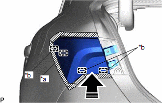
(b) Engage the 3 guides and pin to temporarily install the rear combination light assembly as shown in the illustration.
|
*a | Pin |
|
*b | Guide |
 |
Install in this Direction |
(c) Install the rear combination light assembly with the 2 screws.
(d) Remove the protective tape.
(e) Engage the clamp.
(f) Connect the connector.
2. INSTALL REAR COMBINATION LIGHT COVER
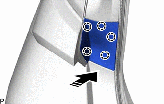
(a) Engage the 5 claws to install the rear combination light cover as shown in the illustration.
 |
Install in this Direction |
3. INSTALL LUGGAGE COMPARTMENT TRIM INNER COVER LH (for LH Side)
Click here 
4. INSTALL LUGGAGE COMPARTMENT TRIM INNER COVER RH (for RH Side)
Click here 
5. INSTALL LUGGAGE TRIM SERVICE HOLE COVER (for RH Side)
for HV Model:
Click here 
6. INSTALL LUGGAGE COMPARTMENT INNER TRIM PAD
Click here 
7. INSTALL REAR FLOOR FINISH PLATE
Click here 
8. INSTALL NO. 1 LUGGAGE COMPARTMENT TRIM HOOK
Click here 
9. INSTALL BAGGAGE HOLDER NET
Click here 
10. INSTALL SPARE WHEEL COVER ASSEMBLY
Click here 
Reassembly
REASSEMBLY
CAUTION / NOTICE / HINT
HINT:
- Use the same procedure for the RH side and LH side.
- The following procedure is for the LH side.
PROCEDURE
1. INSTALL REAR COMBINATION LIGHT SOCKET AND WIRE
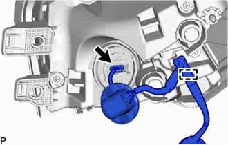
(b) Connect the connector.
(c) Turn the rear combination light socket and wire as shown in the illustration to install it.
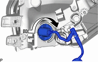
 | Install in this Direction |
Removal
REMOVAL
CAUTION / NOTICE / HINT
HINT:
- Use the same procedure for the RH side and LH side.
- The following procedure is for the LH side.
PROCEDURE
1. REMOVE SPARE WHEEL COVER ASSEMBLY
Click here 
2. REMOVE BAGGAGE HOLDER NET
Click here 
3. REMOVE NO. 1 LUGGAGE COMPARTMENT TRIM HOOK
Click here 
4. REMOVE REAR FLOOR FINISH PLATE
Click here 
5. REMOVE LUGGAGE COMPARTMENT INNER TRIM PAD
Click here 
6. REMOVE LUGGAGE TRIM SERVICE HOLE COVER (for RH Side)
for HV Model:
Click here 
7. REMOVE LUGGAGE COMPARTMENT TRIM INNER COVER RH (for RH Side)
for Gasoline Model:
Click here 
for HV Model:
Click here 
8. REMOVE LUGGAGE COMPARTMENT TRIM INNER COVER LH (for LH Side)
Click here 
9. REMOVE REAR COMBINATION LIGHT COVER
(a) Disengage the 5 claws to remove the rear combination light cover as shown in the illustration.
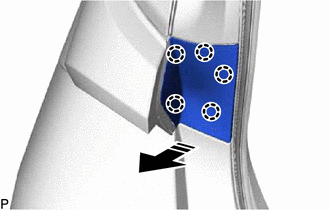
 |
Remove in this Direction |
10. REMOVE REAR COMBINATION LIGHT ASSEMBLY
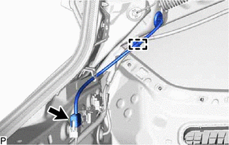
| (a) Disconnect the connector. | |
(b) Disengage the clamp.
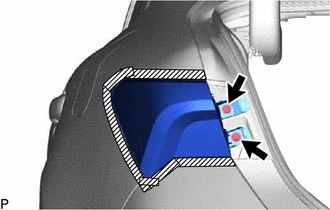
(c) Apply protective tape around the rear combination light assembly as shown in the illustration.
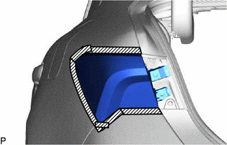
 | Protective Tape |
(e)
Pull the rear combination light assembly toward the rear of the vehicle
as shown in the illustration to disengage the pin and 3 guides and
separate the rear combination light assembly.
NOTICE:
To
prevent the rear combination light assembly from falling when
disengaging the pin and guides, lightly hold the rear combination light
assembly.
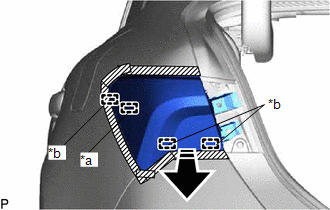
|
*a | Pin |
|
*b | Guide |
 |
Remove in this Direction |
| (f) Disengage the grommet to remove the rear combination light assembly. |
|


