Components
COMPONENTS
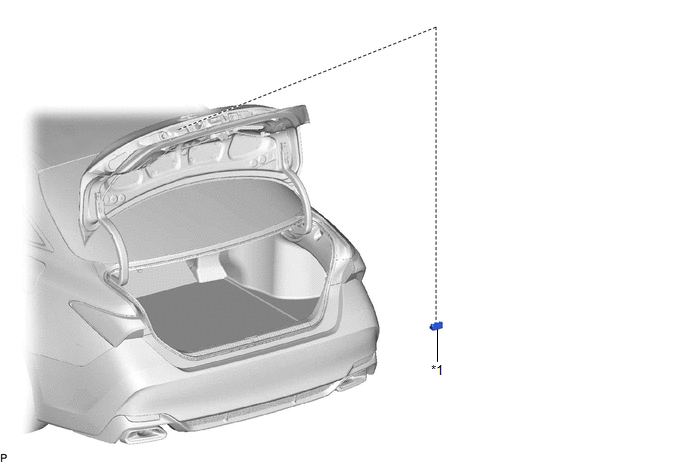
ILLUSTRATION
|
*1 | LICENSE PLATE LIGHT ASSEMBLY |
- | - |
Inspection
INSPECTION
PROCEDURE
1. INSPECT LICENSE PLATE LIGHT ASSEMBLY
|
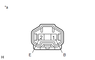
*a | Component without harness connected (License Plate Light Assembly) |
(a) Connect 4 dry-cell batteries (1.5 V) in series.
NOTICE:
Do not use rechargeable batteries as they may not output a voltage of 1.5 V.
(b) Apply 6 V batter voltage to the terminals of the connector and check that the license plate light illuminates.
OK:
|
Measurement Condition | Specified Condition |
|---|---|
|
Positive (+) lead from the batteries → Terminal 1 (B) Negative (-) lead from the batteries → Terminal 2 (E) |
License plate light illuminates |
If the result is not as specified, replace the license plate light assembly.
Installation
INSTALLATION
CAUTION / NOTICE / HINT
HINT:
PROCEDURE
1. INSTALL LICENSE PLATE LIGHT ASSEMBLY
(a) Engage the 2 claws to install the license plate light assembly.
(b) Connect the connector.
2. INSTALL LUGGAGE COMPARTMENT DOOR OUTSIDE GARNISH SUB-ASSEMBLY
Click here

Removal
REMOVAL
CAUTION / NOTICE / HINT
HINT:
PROCEDURE
1. REMOVE LUGGAGE COMPARTMENT DOOR OUTSIDE GARNISH SUB-ASSEMBLY
Click here 
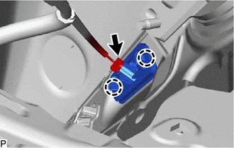
2. REMOVE LICENSE PLATE LIGHT ASSEMBLY
| (a) Disconnect the connector. |
|
(b) Disengage the 2 claws to remove the license plate light assembly.
Toyota Avalon (XX50) 2019-2022 Service & Repair Manual > Meter / Gauge System(for Gasoline Model): Lost Communication with EMV Missing Message (B132187). Fuel Sender Circuit Open (B150013). Turn Signal Light Circuit Current Below Threshold (B150718)
Lost Communication with EMV Missing Message (B132187) DESCRIPTION The combination meter assembly and radio and display receiver assembly communicate via local bus communication. This allows audio and visual system information to be displayed on the multi-information display. This DTC is stored when ...