Components
COMPONENTS
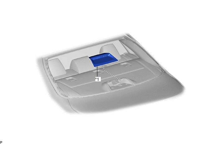
ILLUSTRATION
|
*1 | CENTER STOP LIGHT SET |
- | - |
Inspection
INSPECTION
PROCEDURE
1. INSPECT CENTER STOP LIGHT SET
|
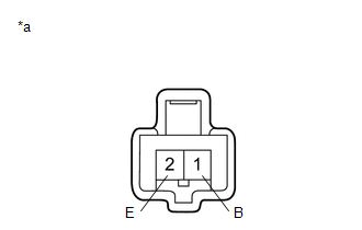
*a | Component without harness connected (Center Stop Light Set) |
(a) Apply auxiliary battery voltage to the center stop light set and check that the light illuminates.
OK:
|
Measurement Condition | Specified Condition |
|---|---|
|
Auxiliary battery positive (+) → Terminal 1 (B) Auxiliary battery negative (-) → Terminal 2 (E) |
Center stop light illuminates |
If the result is not as specified, replace the center stop light set.
Installation
INSTALLATION
PROCEDURE
1. INSTALL CENTER STOP LIGHT SET
(a) Engage the 2 guides as shown in the illustration.
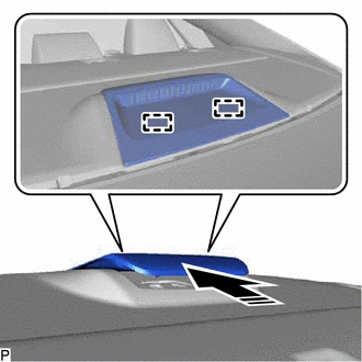
 |
Install in this Direction |
(b) Connect the connector.
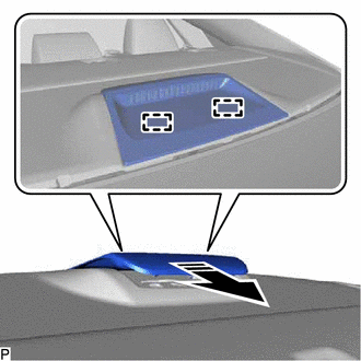
(c) Engage the 2 claws as shown in the illustration to install the center stop light set.
|
|
Install in this Direction |
Removal
REMOVAL
PROCEDURE
1. REMOVE CENTER STOP LIGHT SET
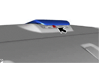
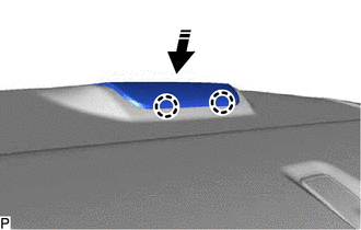
(a) Using a moulding remover, disengage the 2 claws as shown in the illustration.
 |
Remove in this Direction |
| (b) Disconnect the connector. |
|
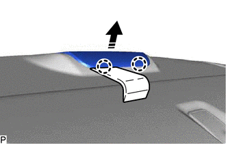
(c) Disengage the 2 guides as shown in the illustration to remove the center stop light set.
|
|
Remove in this Direction |
Toyota Avalon (XX50) 2019-2022 Service & Repair Manual > P710 Hybrid Transmission / Transaxle: Transmission Control Cable
Adjustment ADJUSTMENT PROCEDURE 1. SECURE VEHICLE (a) Fully apply the parking brake and chock a wheel. CAUTION: Make sure to apply the parking brake and chock a wheel before performing this procedure. If the vehicle is not secure and the shift lever is moved to N, the vehicle may suddenly move, poss ...