Components
COMPONENTS
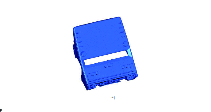
ILLUSTRATION
|
*1 | HAZARD WARNING SWITCH ASSEMBLY (RADIO AND DISPLAY RECEIVER ASSEMBLY) |
- | - |
Inspection
INSPECTION
PROCEDURE
1. INSPECT HAZARD WARNING SWITCH ASSEMBLY (RADIO AND DISPLAY RECEIVER ASSEMBLY)
|
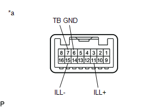
*a | Component without harness connected (Hazard Warning Switch Assembly (Radio and Display Receiver Assembly)) |
(a) Check the switch.
(1) Measure the resistance according to the value(s) in the table below.
Standard Resistance:
|
Tester Connection | Condition |
Specified Condition |
|---|---|---|
|
7 (TB) - 6 (GND) | Hazard warning switch off |
10 kΩ or higher |
|
Hazard warning switch on |
Below 1 Ω |
If the result is not as specified, replace the hazard warning switch assembly (radio and display receiver assembly).
(b) Inspect the switch illumination.
(1) Apply auxiliary battery voltage to the hazard warning switch assembly (radio and display receiver assembly) and check that the switch illuminates.
OK:
|
Measurement Condition | Specified Condition |
|---|---|
|
Auxiliary battery positive (+) → Terminal 11 (ILL+) Auxiliary battery negative (-) → Terminal 15 (ILL-) |
Illuminates |
If the result is not as specified, replace the hazard warning switch assembly (radio and display receiver assembly).
Installation
INSTALLATION
PROCEDURE
1. INSTALL HAZARD WARNING SWITCH ASSEMBLY (RADIO AND DISPLAY RECEIVER ASSEMBLY)
Click here 
Removal
REMOVAL
PROCEDURE
1. REMOVE HAZARD WARNING SWITCH ASSEMBLY (RADIO AND DISPLAY RECEIVER ASSEMBLY)
Click here 
Toyota Avalon (XX50) 2019-2022 Service & Repair Manual > Motor Generator Control System: Generator Inverter Stuck On (P0A7A9E,P1C5F19)
DTC SUMMARY MALFUNCTION DESCRIPTION This DTC indicates that a large current flowed in the inverter generator. The cause of this malfunction may be one of the following: Area Main Malfunction Description Hybrid vehicle transaxle assembly Open or short circuit in the generator coils Generator (MG1) in ...


