Installation
INSTALLATION
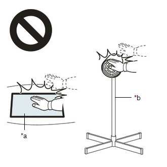
CAUTION / NOTICE / HINT
HINT:
- Use the same procedure for the RH side and LH side.
- The following procedure is for the LH side.
PROCEDURE
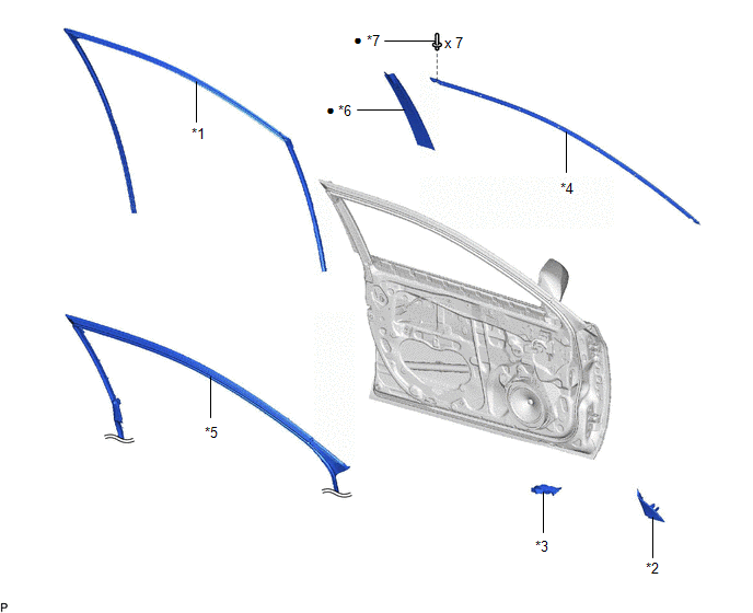
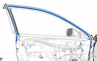
1. INSTALL FRONT DOOR UPPER WINDOW FRAME MOULDING
(a) Engage the claw and guide to temporarily install the front door upper window frame moulding to the door frame.
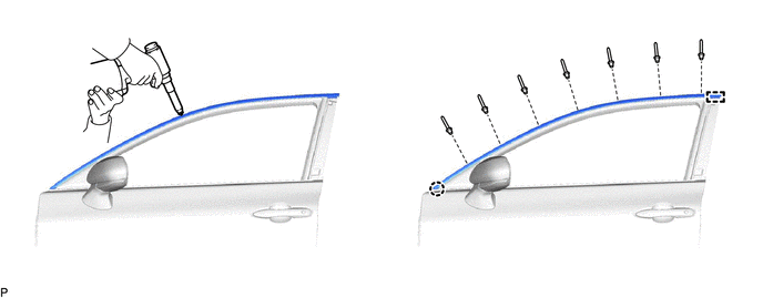
(b)
Using an air riveter or hand riveter with a nose piece, install the
front door upper window frame moulding with 7 new rivets.
HINT:
If
the mandrel of the rivet does not come off on the first operation of
the riveter, slide the riveter forward on the mandrel and operate it
again.
NOTICE:
- Do not pry the rivet with the riveter, as this will cause damage to the riveter and mandrel.
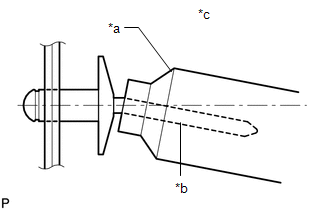
|
*a |
Riveter |
|
*b |
Mandrel |
|
*c |
Incorrect |
- Confirm that the rivets are seated properly against the moulding.
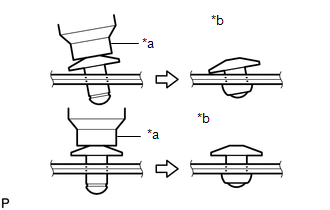
- Do not tilt the riveter when installing the rivet to the moulding.
- Do not leave any space between the rivet head and moulding.
- Do not leave any space between the moulding and door frame. Firmly hold the 2 items together while installing the rivet.
2. INSTALL FRONT DOOR WINDOW FRAME MOULDING (CENTER PILLAR SIDE)
HINT:
When
installing a new front door window frame moulding (center pillar side),
heat the vehicle body and front door window frame moulding (center
pillar side) using a heat light.
Heating Temperature |
Item | Temperature |
|
Vehicle Body | 40 to 60°C (104 to 140°F) |
|
Front Door Window Frame Moulding (Center Pillar Side) |
20 to 30°C (68 to 86°F) |
CAUTION:
- Do not touch the heat light and heated parts, touching the heat light may result in burns.
- Touching heated parts for a long time may result in burns.

|
*a | Heated Part |
|
*b | Heat Light |
NOTICE:
Do not heat the vehicle body or front door window frame moulding (center pillar side) excessively.
(a) Clean the vehicle body surface.
(1) Using a heat light, heat the vehicle body surface.
(2) Remove any double-sided tape from the vehicle body.
(3) Wipe off any tape adhesive residue with cleaner.
(b) Install a new front door window frame moulding (center pillar side).
(1) Using a heat light, heat the vehicle body and front door window frame moulding (center pillar side).
(2) Remove the release paper from the front door window frame moulding (center pillar side).
HINT:
After removing the release paper, keep the exposed adhesive free from foreign matter.
| (3)
Engage the clip and attach the double-sided tape and caulking sponge to
install the front door window frame moulding (center pillar side). HINT:
Press the front door window frame moulding (center pillar side) firmly to install it. |
 |
|
*a | Double-sided Tape | |
*b | Caulking Sponge | | |
3. CONNECT FRONT DOOR WEATHERSTRIP
(a) Engage the 2 clips and connect the front door weatherstrip.
4. INSTALL FRONT DOOR GLASS RUN
Click here

5. INSTALL FRONT DOOR PANEL PROTECTOR
Click here
6. INSTALL FRONT DOOR LOWER FRAME BRACKET GARNISH
Click here
7. INSTALL FRONT DOOR BELT MOULDING ASSEMBLY
Click here
Removal
REMOVAL
CAUTION / NOTICE / HINT
The
necessary procedures (adjustment, calibration, initialization, or
registration) that must be performed after parts are removed and
installed, or replaced during front door window frame moulding
removal/installation are shown below.
Necessary Procedure After Parts Removed/Installed/Replaced (for Gasoline Model) |
Replaced Part or Performed Procedure |
Necessary Procedure | Effect/Inoperative Function When Necessary Procedures are not Performed |
Link |
|
*: When performing learning using the Techstream.
Click here  |
|
Disconnect cable from negative battery terminal |
Perform steering sensor zero point calibration |
Lane Departure Alert System (w/ Steering Control) |
|
|
Pre-collision System |
|
Intelligent Clearance Sonar System* |
|
Lighting System (for Gasoline Model with Cornering Light) |
|
Memorize steering angle neutral point |
Parking Assist Monitor System |
|
|
Panoramic View Monitor System |
|
- Front door glass sub-assembly
- Front door glass run
| Initialize power window control system |
- Auto up and down function
- Jam protection function
- Remote control function
- Key-linked function
- Wireless transmitter-linked function
- Key-off operation function
- Catch protection function
- Window open warning function
|
|
Necessary Procedure After Parts Removed/Installed/Replaced (for HV Model) |
Replaced Part or Performed Procedure |
Necessary Procedure | Effect/Inoperative Function When Necessary Procedures are not Performed |
Link |
|
*: When performing learning using the Techstream.
Click here |
|
Disconnect cable from negative auxiliary battery terminal |
Perform steering sensor zero point calibration |
Lane Departure Alert System (w/ Steering Control) |
|
|
Pre-collision System |
|
Intelligent Clearance Sonar System* |
|
Lighting System (for HV Model with Cornering Light) |
|
Memorize steering angle neutral point |
Parking Assist Monitor System |
|
|
Panoramic View Monitor System |
|
- Front door glass sub-assembly
- Front door glass run
| Initialize power window control system |
- Auto up and down function
- Jam protection function
- Remote control function
- Key-linked function
- Wireless transmitter-linked function
- Key-off operation function
- Catch protection function
- Window open warning function
|
|
HINT:
- Use the same procedure for the RH side and LH side.
- The following procedure is for the LH side.
PROCEDURE
1. REMOVE FRONT DOOR BELT MOULDING ASSEMBLY
Click here
2. REMOVE FRONT DOOR LOWER FRAME BRACKET GARNISH
Click here
3. REMOVE FRONT DOOR PANEL PROTECTOR
Click here
4. REMOVE FRONT DOOR GLASS RUN
Click here
5. DISCONNECT FRONT DOOR WEATHERSTRIP
| (a) Disengage the 2 clips and disconnect the front door weatherstrip. |
|
6. REMOVE FRONT DOOR WINDOW FRAME MOULDING (CENTER PILLAR SIDE)
HINT:
When
removing the front door window frame moulding (center pillar side),
heat the vehicle body and front door window frame moulding (center
pillar side) using a heat light.
Heating Temperature |
Item | Temperature |
|
Vehicle Body | 40 to 60°C (104 to 140°F) |
|
Front Door Window Frame Moulding (Center Pillar Side) |
20 to 30°C (68 to 86°F) |
CAUTION:
- Do not touch the heat light and heated parts, touching the heat light may result in burns.
- Touching heated parts for a long time may result in burns.
|
*a | Heated Part |
|
*b | Heat Light |
NOTICE:
Do not heat the vehicle body or front door window frame moulding (center pillar side) excessively.
(a) Using a heat light, heat the front door window frame moulding (center pillar side).
| (b)
Using a moulding remover, disengage the clip and separate the
double-sided tape and caulking sponge to remove the front door window
frame moulding (center pillar side). |
 |
|
*a | Double-sided Tape | |
*b | Caulking Sponge | | |
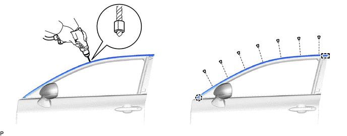
7. REMOVE FRONT DOOR UPPER WINDOW FRAME MOULDING
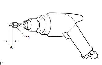
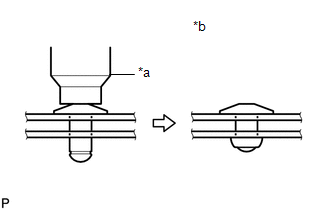
(a) Insert a 4.0 mm (0.157 in.) drill bit into a drill.
| (b) Tape the 4.0 mm (0.157 in.) drill bit 5.0 mm (0.197 in.) from the tip as shown in the illustration.
Standard Measurement: |
Area | Measurement | |
A | 5.0 mm (0.197 in.) |
NOTICE: Tape the 4.0 mm (0.157 in.) drill bit to prevent the drill bit from going too deep. |
|
(c) Lightly press the drill bit against the rivets to drill off the rivet flanges, and remove the 7 rivets.
CAUTION:
Be careful of the drilled rivets, as they may be hot.
NOTICE:
- Pressing the drill too firmly will cause the rivet to turn and result in the rivet not being drilled through.
- Prying the rivets with the drill may damage the rivet installation holes or drill bit.
(d) Using a vacuum cleaner, remove the rivet fragments and shavings from the drilled areas.
(e) Disengage the claw and guide to remove the front door upper window frame moulding from the door frame.