Components
COMPONENTS
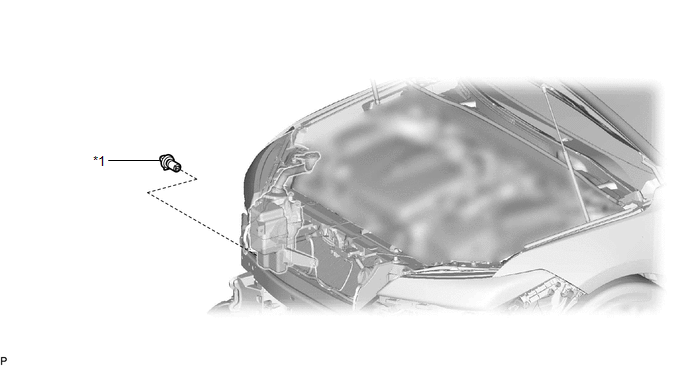
ILLUSTRATION
|
*1 | LEVEL WARNING SWITCH ASSEMBLY |
- | - |
Inspection
INSPECTION
PROCEDURE
1. INSPECT LEVEL WARNING SWITCH ASSEMBLY
HINT:
This check should be performed with the level warning switch assembly installed on the washer jar.
| (a) Fill the washer jar with washer fluid. |
 |
|
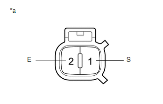
*a | Component without harness connected
(Level Warning Switch Assembly) | | |
(b) Measure the resistance according to the value(s) in the table below.
Standard Resistance:
|
Tester Connection | Condition |
Specified Condition |
|
1 (S) - 2 (E) | Fluid volume is 600 to 800 cc (36.6 to 48.8 cu. in.) or higher* |
10 kΩ or higher |
|
Fluid volume is 600 to 800 cc (36.6 to 48.8 cu. in.) or lower* |
Below 1 Ω |
HINT:
*:
The level warning switch assembly begins operating when the fluid
volume is 600 to 800 cc (36.6 to 48.8 cu. in.) depending on the vehicle
condition.
If the result is not as specified, replace the level warning switch assembly.
Installation
INSTALLATION
PROCEDURE
1. INSTALL LEVEL WARNING SWITCH ASSEMBLY
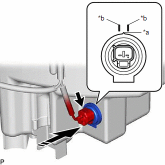
(a) Install the level warning switch assembly as shown in the illustration.
|
*a | Protrusion |
|
*b | Marking |
 |
Install in this Direction |
NOTICE:
Make sure that the protrusion of the level warning switch assembly is between the 2 markings.
(b) Connect the connector.
2. ADD WASHER FLUID
Click here

3. INSTALL FRONT BUMPER ASSEMBLY
Click here
Removal
REMOVAL
CAUTION / NOTICE / HINT
The
necessary procedures (adjustment, calibration, initialization or
registration) that must be performed after parts are removed and
installed, or replaced during level warning switch assembly
removal/installation are shown below.
Necessary Procedure After Parts Removed/Installed/Replaced (for Gasoline Model) |
Replaced Part or Performed Procedure |
Necessary Procedure | Effect/Inoperative Function When Necessary Procedures are not Performed |
Link |
|
Front bumper assembly |
- Measurement of ultrasonic sensor detection angle
- Ultrasonic sensor detection angle registration
|
- Intelligent Clearance Sonar System
- Intuitive Parking Assist System
|
 |
|
Front television camera view adjustment |
Panoramic View Monitor System |
|
Necessary Procedure After Parts Removed/Installed/Replaced (for HV Model) |
Replaced Part or Performed Procedure |
Necessary Procedure | Effect/Inoperative Function When Necessary Procedures are not Performed |
Link |
|
Front bumper assembly |
- Measurement of ultrasonic sensor detection angle
- Ultrasonic sensor detection angle registration
|
- Intelligent Clearance Sonar System
- Intuitive Parking Assist System
|
|
|
Front television camera view adjustment |
Panoramic View Monitor System |
|
PROCEDURE
1. REMOVE FRONT BUMPER ASSEMBLY
Click here
2. DRAIN WASHER FLUID
Click here
3. REMOVE LEVEL WARNING SWITCH ASSEMBLY
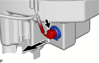
(a) Disconnect the connector.
 |
Remove in this Direction |
(b) Remove the level warning switch assembly as shown in the illustration.


