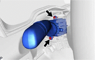
Components
COMPONENTS
ILLUSTRATION
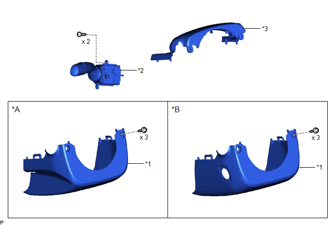
|
*A | for Manual Tilt and Manual Telescopic Steering Column |
*B | for Power Tilt and Power Telescopic Steering Column |
|
*1 | LOWER STEERING COLUMN COVER |
*2 | TURN SIGNAL SWITCH |
|
*3 | UPPER STEERING COLUMN COVER |
- | - |
Inspection
INSPECTION
PROCEDURE
1. INSPECT TURN SIGNAL SWITCH
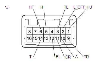
|
*a | Component without harness connected
(Turn Signal Switch) |
(a) Measure the resistance according to the value(s) in the table below.
Standard Resistance:
Light Control Switch |
Tester Connection | Condition |
Specified Condition |
|
2 (L_OFF) - 12 (EL)*1 |
Light control switch in DRL OFF position |
Below 1 Ω |
|
10 (A) - 12 (EL) | Light control switch in AUTO position |
Below 1 Ω |
|
14 (T) - 12 (EL) | Light control switch in tail position |
Below 1 Ω |
|
5 (H) - 12 (EL) | Light control switch in head position |
Below 1 Ω |
Dimmer Switch |
Tester Connection | Condition |
Specified Condition |
|
6 (HF) - 12 (EL) | Dimmer switch in high flash position |
Below 1 Ω |
|
1 (HU) - 12 (EL) | Dimmer switch in high position |
Below 1 Ω |
Turn Signal Switch |
Tester Connection | Condition |
Specified Condition |
|
9 (TR) - 12 (EL) | Turn signal switch in neutral position |
10 kΩ or higher |
|
3 (TL) - 12 (EL) | Turn signal switch in neutral position |
10 kΩ or higher |
|
9 (TR) - 12 (EL) | Turn signal switch in right turn position |
Below 1 Ω |
|
9 (TR) - 12 (EL) | Turn signal switch in full right turn position |
Below 1 Ω |
|
9 (TR) - 11 (CR) | Turn signal switch in full right turn position |
Below 1 Ω |
|
11 (CR) - 12 (EL) | Turn signal switch in full right turn position |
Below 1 Ω |
|
3 (TL) - 12 (EL) | Turn signal switch in left turn position |
Below 1 Ω |
|
3 (TL) - 12 (EL) | Turn signal switch in full left turn position |
Below 1 Ω |
|
3 (TL) - 11 (CR) | Turn signal switch in full left turn position |
Below 1 Ω |
|
11 (CR) - 12 (EL) | Turn signal switch in full left turn position |
Below 1 Ω |
- *1: w/ Light Control Switch DRL OFF Position
HINT:
- The left turn or right turn condition indicates a condition in which the
turn signal switch will return to the neutral position after releasing
your hand from the turn signal switch (turn signal switch is operated
approximately 7°).
- The full left turn or full right turn condition indicates a condition in
which the turn signal switch will not return to the neutral position
after releasing your hand from the turn signal switch (turn signal
switch is operated 12°).
If the result is not as specified, replace the turn signal switch.
Installation
INSTALLATION
PROCEDURE
1. INSTALL TURN SIGNAL SWITCH
(a) Engage the claw as shown in the illustration.
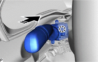
 |
Install in this Direction |
(b) Install the turn signal switch with the 2 screws.
2. INSTALL UPPER STEERING COLUMN COVER
Click here

3. INSTALL LOWER STEERING COLUMN COVER
Click here 
4. CUSTOMIZE POWER TILT AND POWER TELESCOPIC STEERING COLUMN SYSTEM (for Power Tilt and Power Telescopic Steering Column)
Click here 
Removal
REMOVAL
PROCEDURE
1. CHANGE POWER TILT AND POWER TELESCOPIC STEERING COLUMN SYSTEM SETTINGS (for Power Tilt and Power Telescopic Steering Column)
Click here 
2. REMOVE LOWER STEERING COLUMN COVER
Click here 
3. REMOVE UPPER STEERING COLUMN COVER
Click here 
4. REMOVE TURN SIGNAL SWITCH
(b)
Using a screwdriver with its tip wrapped with protective tape,
disengage the claw and remove the turn signal switch as shown in the
illustration.
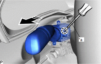
|
*a | Protective Tape |
 |
Remove in this Direction |


