Components
COMPONENTS
ILLUSTRATION

|
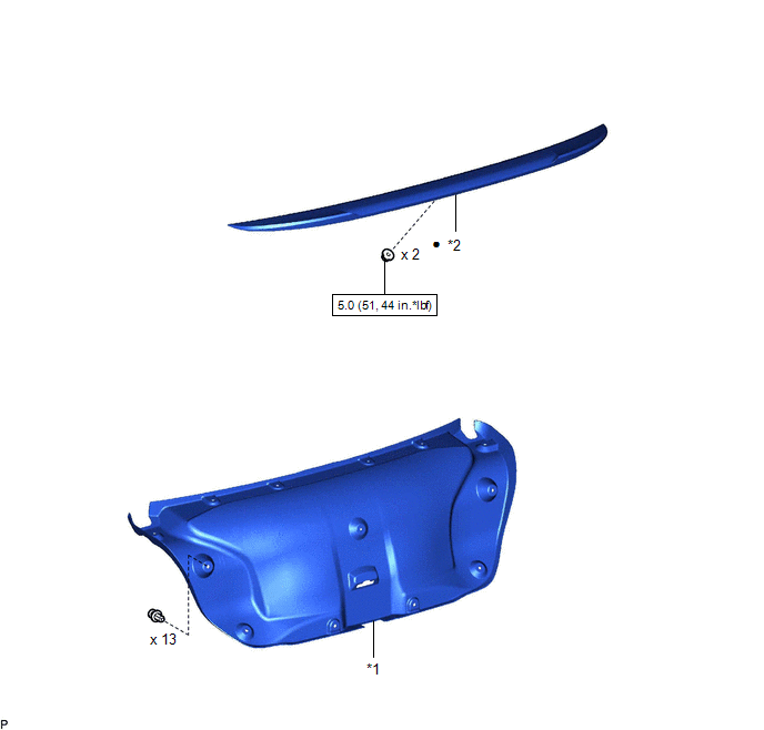
*1 | LUGGAGE COMPARTMENT DOOR COVER |
*2 | REAR SPOILER SUB-ASSEMBLY |
 |
N*m (kgf*cm, ft.*lbf): Specified torque |
â—Ź | Non-reusable part |
Installation
INSTALLATION
PROCEDURE
1. INSTALL REAR SPOILER SUB-ASSEMBLY
HINT:
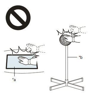
When installing a new rear spoiler sub-assembly, heat the luggage compartment door panel and rear spoiler sub-assembly using a heat light.
Heating Temperature|
Item | Temperature |
|---|---|
|
Luggage Compartment Door Panel |
40 to 60°C (104 to 140°F) |
|
Rear Spoiler Sub-assembly |
20 to 30°C (68 to 86°F) |
CAUTION:

|
*a | Heated Part |
|
*b | Heat Light |
NOTICE:
Do not heat the luggage compartment door panel or rear spoiler sub-assembly excessively.
(a) Clean the luggage compartment door panel surface.
(1) Using a heat light, heat the luggage compartment door panel surface.
(2) Remove any double-sided tape from the luggage compartment door panel.
(3) Wipe off any tape adhesive residue with cleaner.
(b) Using a brush or felt, apply primer or equivalent to the rear spoiler sub-assembly installation area.
NOTICE:
(c) Remove the release paper from a new rear spoiler sub-assembly.
(d) Attach the double-sided tape and engage the 5 clips to install the rear spoiler sub-assembly.
HINT:
Press the rear spoiler sub-assembly firmly to install it.
(e) Install the rear spoiler sub-assembly with the 2 nuts.
Torque:
5.0 N·m {51 kgf·cm, 44 in·lbf}
2. INSTALL LUGGAGE COMPARTMENT DOOR COVER
Click here 
Removal
REMOVAL
PROCEDURE
1. REMOVE LUGGAGE COMPARTMENT DOOR COVER
Click here

2. REMOVE REAR SPOILER SUB-ASSEMBLY
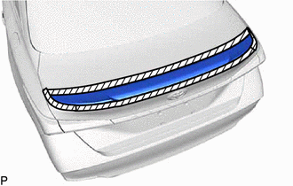
(a) Apply protective tape around the rear spoiler sub-assembly as shown in the illustration.

 | Protective Tape |
| (b) Remove the 2 nuts. |
|
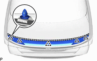
(c) Separate the double-sided tape and disengage the 5 clips to remove the rear spoiler sub-assembly.

 | Double-sided Tape |
Toyota Avalon (XX50) 2019-2022 Service & Repair Manual > Hybrid Control System: Drive Motor "A" Inverter Voltage Sensor Voltage Out of Range (P0D2D1C)
DTC SUMMARY MALFUNCTION DESCRIPTION The hybrid vehicle control ECU detects a VH sensor malfunction. The cause of this malfunction may be one of the following: Inverter voltage sensor internal circuit malfunction Voltage sensor malfunction Motor generator control ECU (MG ECU) malfunction Communicatio ...